The Magnet Switch turns your rocket's electronics on and off from outside the rocket. Hold a magnet against the airframe for a couple of seconds and you're on, with no hole to drill for a screw switch and no opening up the bay on the pad.
There is an optional push button to hold, or you can connect an external button or sensor too.
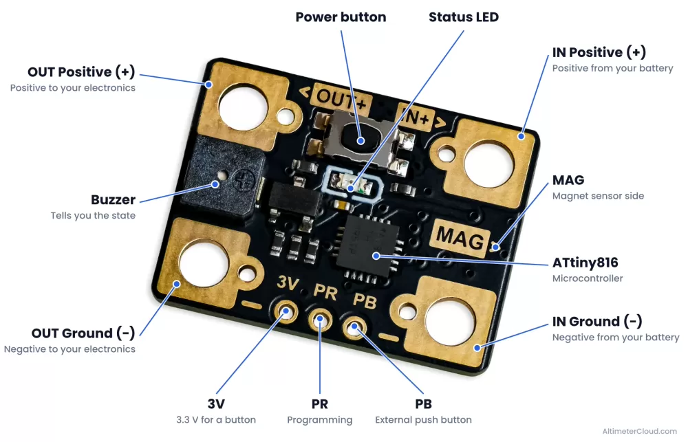
Everything you need to connect to, as it is labelled on the board.
It sits between your battery and your electronics and switches the positive side, while the negative runs straight through the board. As well as the magnet there's a push button on the board and a connection for an external button, so you can use whichever suits your rocket.
At its heart is an ATtiny816 microcontroller that's asleep nearly all of the time. It wakes once a second to check the magnet sensor and the buttons, then goes straight back to sleep, which is how it draws so little while it's off. It's also why you need to hold the magnet there for a moment rather than just swipe it past. We've added the programming pin (PG) and the current code, so if you want to edit how it works for your own use you can do so.
The Schematic and code is available in the documents section of this manual.
Wiring it in
Your battery goes to the IN side and your electronics go to the OUT side. Both − pads are the same connection, so use whichever is handiest.
| Label | Connects to |
|---|---|
| IN+ | Battery positive |
| OUT+ | Positive to your altimeter or flight computer |
| − | Battery negative and the negative to your electronics |
| PB | An external button or a 3.3 V signal, if you want one |
| 3V | The other side of an external button |
| PR | Programming only, see the programming page |
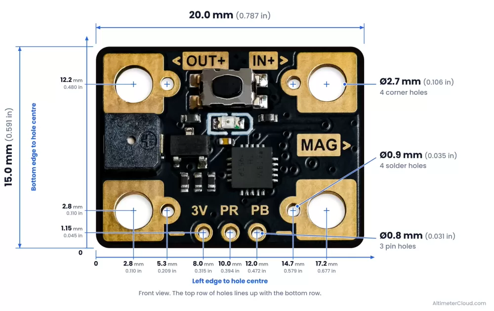
Each corner pad has an M2 hole with a smaller solder hole beside it. Solder your wires into the holes, or use ring terminals under M2 screws, which will hold the board down at the same time. The pads are live, so don't screw the board straight onto anything conductive such as carbon fibre or metal.
The input is protected against reversed polarity, so connecting the battery backwards won't hurt it. It just won't do anything until you swap the wires over.
Turning it on and off
Hold the magnet against the MAG side of the board, or hold down the power button on the board, or hold your external button, for about 2 seconds. The switch changes state and tells you which way it went.
| Buzzer | LED | |
|---|---|---|
| Turning on | Five quick tones over about a second | Lit during the tones |
| While on | A short double beep about every 10 seconds | A short flash about every 2 seconds |
| Turning off | One long tone of 2 seconds | Goes out |
| While off | Silent | Off |
The output changes the moment the tones start. Once you hear them, take the magnet away. The switch ignores the magnet and buttons for the next 5 to 6 seconds, but after that it's listening again, so a magnet left in place will change it straight back.
Finding the magnet spot
Any small neodymium magnet will do, and it doesn't matter which pole faces the board. The sensor looks for field passing through the board, so hold the flat face of the magnet towards the board rather than its edge. The arrow beside MAG shows which side of the board the sensor is on.
How far away it works depends on your magnet, so try it with the board fitted in your rocket, then mark the spot on the outside of the airframe so you can find it again on the pad.
It remembers where it was
Every time it changes state the switch saves that state, so a lost connection or a battery swap won't change anything. If it was on when the power went, it's on again as soon as the power comes back. It doesn't play the tones when that happens, it just carries on with its flashes and beeps.
The onboard capacitors also keep the microcontroller running through short power blips, about 5 seconds on our bench, so a battery connector that jumps under a hard knock doesn't make it restart.
Adding an external button
Wire a momentary push button between the 3V and PB holes and it works just like the button on the board. PB will also take a 3.3 V signal from another board, as long as the two share a ground.
Make sure it's a momentary button rather than a latching switch. If PB stays high the switch will keep changing state every 10 seconds or so.
If something's not right
- Your electronics stay on whatever the switch does. IN and OUT are swapped and power is feeding through from the OUT side. No harm done, just swap them over.
- Nothing happens when you hold the magnet. Give it a full 2 seconds, and if you've just changed state wait 6 seconds first. After that try it closer, with the flat face towards the board, or with a stronger magnet.
- It changed state on its own. Check for magnets nearby, including magnetic catches and tools, and check nothing is pressing on the power button.
Specifications
| Magnet Switch | |
|---|---|
| Input voltage | 3 to 16.8 V (1S to 4S LiPo) |
| Reverse polarity | Protected on the input |
| Output | Switches the positive side through a P-channel MOSFET |
| Draw while off | About 4.5 µA |
| Draw while on | About 0.7 mA, most of that being the buzzer, plus whatever your electronics draw |
| Magnet sensor | Either pole, 1.8 mT typical |
| Board size | 20 × 15 mm |