Configuration de l'Arduino IDE pour ESP32-S2, S3 et C6
Configuration de l'Arduino IDE pour le travail avec ESP32
Guide étape par étape pour installer l'Arduino IDE, ajouter la prise en charge de la carte ESP32 et télécharger un premier sketch sur un ESP32-S2, ESP32-S3 ou ESP32-C6.
Si vous n'avez jamais utilisé l'Arduino IDE auparavant, le processus paraît plus compliqué qu'il ne l'est réellement. Il y a trois étapes : installer l'IDE, installer le package de prise en charge de la carte ESP32, puis choisir la bonne carte et le bon port. La plupart des problèmes rencontrés par les utilisateurs surviennent à la dernière étape, c'est pourquoi les paramètres de la carte sont expliqués en détail plus bas.
Ce guide suppose que vous utilisez Arduino IDE 2, qui est la version actuelle et celle que vous devriez utiliser pour le travail avec ESP32. L'ancien IDE 1.8.x fonctionne toujours mais le gestionnaire de cartes est plus lent et l'éditeur est bien moins utile.
Ce qu'il vous faut avant de commencer
- Une machine Windows, macOS ou Linux avec quelques gigaoctets d'espace libre. Le noyau ESP32 et ses chaînes d'outils sont un téléchargement volumineux.
- Un câble USB capable de transférer des données. C'est un point qui pose constamment problème. De nombreux câbles USB-C fournis avec les téléphones et les chargeurs portables sont à charge uniquement, et la carte n'apparaîtra tout simplement jamais.
- Une carte ESP32. Les instructions ci-dessous couvrent les variantes S2, S3 et C6.
- Une connexion Internet raisonnablement bonne pour le téléchargement initial.
Étape 1 : Installer l'Arduino IDE
Allez sur arduino.cc/en/software et téléchargez la version actuelle pour votre système d'exploitation. Le site vous proposera d'abord une page de donation. Vous pouvez ignorer cela et aller directement au téléchargement.
- Windows : prenez l'installateur plutôt que le ZIP. Acceptez les invites de pilote si elles apparaissent lors de l'installation.
- macOS : ouvrez l'image disque et glissez-déposez l'application dans Applications. Au premier lancement, vous devrez peut-être l'approuver dans Confidentialité et sécurité.
- Linux : l'AppImage pose le moins de problèmes. Marquez-la comme exécutable et lancez-la. Vous devrez aussi vous ajouter au groupe dialout, ce qui est expliqué sous les pilotes ci-dessous.
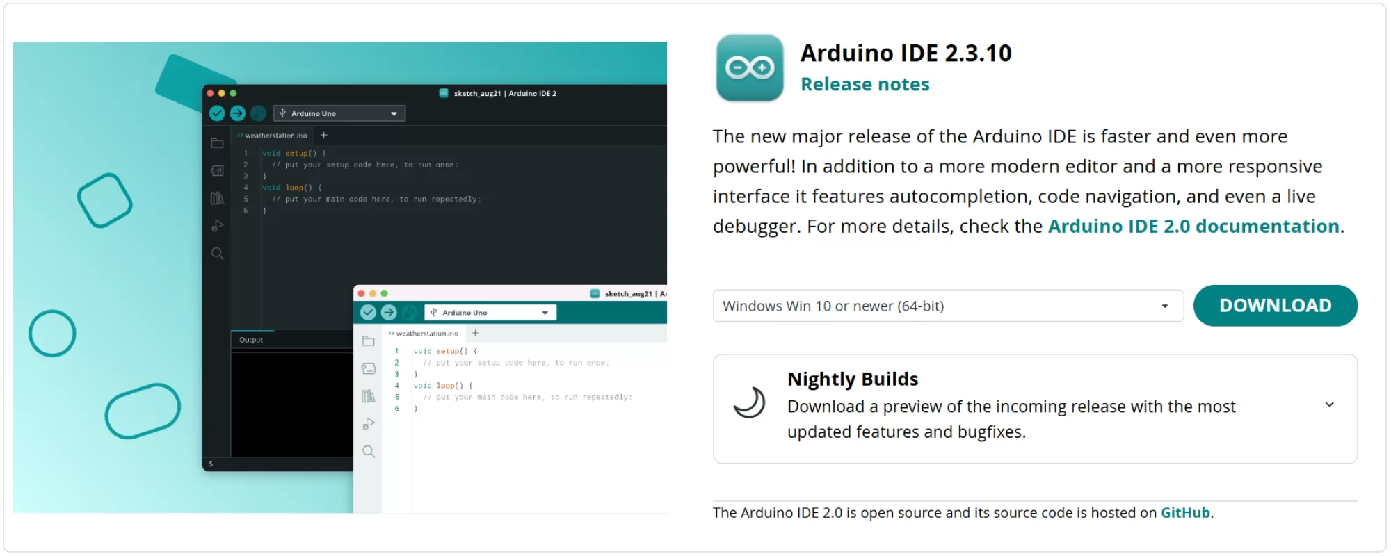
Figure 1 : La page de téléchargement sur arduino.cc
Lancez l'IDE une fois l'installation terminée. Il créera un dossier sketchbook dans votre zone de documents et un dossier de paramètres caché. Il est utile de savoir où se trouve le dossier de paramètres, car si la prise en charge de la carte se retrouve en désordre, la correction la plus rapide consiste à en supprimer une partie et recommencer :
- Windows :
%LOCALAPPDATA%\Arduino15 - macOS :
~/Library/Arduino15 - Linux :
~/.arduino15
Étape 2 : Installer le noyau ESP32
Ouvrez le gestionnaire de cartes. C'est la deuxième icône en haut de la barre d'outils de gauche, ou Outils > Carte > Gestionnaire de cartes. Tapez esp32 dans la zone de recherche et attendez un moment pour que la liste se charge.
Les anciens guides, y compris beaucoup qui apparaissent toujours près du haut des résultats de recherche, vous disent de coller une URL personnalisée dans Préférences avant de pouvoir faire cela. Sur les versions actuelles de l'IDE, c'est souvent inutile, alors essayez d'abord la recherche et voyez ce qui revient. Si le package Espressif est listé, continuez simplement. S'il ne l'est pas, il y a un court détour ci-dessous qui le réglera.
Vous verrez probablement deux entrées, et il importe de choisir la bonne :
- Arduino ESP32 Boards, par Arduino. Ce package ne contient que l'Arduino Nano ESP32. Il ne vous donnera pas les entrées du module de développement S2, S3 ou C6. À moins que vous possédiez un Nano ESP32, ce n'est pas celui-ci.
- esp32, par Espressif Systems. C'est celui dont vous avez besoin. Choisissez la version 3.x la plus récente dans la liste déroulante de version et cliquez sur Installer.
Le téléchargement fait plusieurs centaines de mégaoctets une fois les chaînes d'outils du compilateur incluses, alors laissez du temps. La barre de progression reste immobile pendant de longues périodes pendant qu'elle décompresse. Ne fermez pas l'IDE en cours de route. S'il échoue à mi-chemin, relancez-le plutôt que d'supposer que cela a fonctionné.
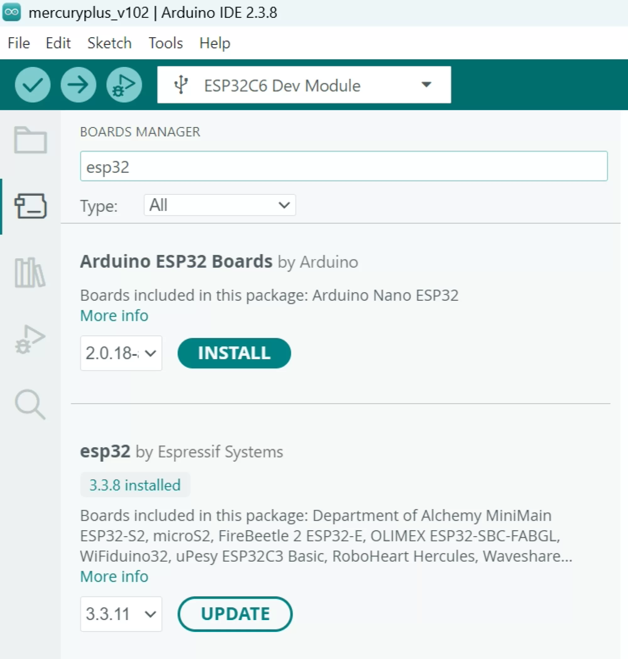
Figure 2 : Deux packages, noms similaires. Vous voulez esp32 par Espressif Systems.
Si le package Espressif n'apparaît pas
Pointez l'IDE vers l'index des packages propre d'Espressif à la main. Cela ne cause aucun dommage de le faire même si le package était déjà affiché, donc si vous préférez le configurer une fois et ne plus y penser, allez-y.
Allez sur Fichier > Préférences, ou sur macOS Arduino IDE > Paramètres. Trouvez le champ intitulé URL additionnelles du gestionnaire de cartes et ajoutez ceci :
https://espressif.github.io/arduino-esp32/package_esp32_index.json
Si vous avez déjà d'autres URL là-dedans, par exemple pour la prise en charge d'ATtiny ou ESP8266, cliquez sur la petite icône au bout droit du champ pour ouvrir une boîte plus grande et mettez chaque URL sur sa propre ligne. Cliquez sur OK, puis redémarrez l'IDE, car il ne récupère un index nouvellement ajouté que au démarrage. Recherchez esp32 dans le gestionnaire de cartes à nouveau et l'entrée Espressif sera là.
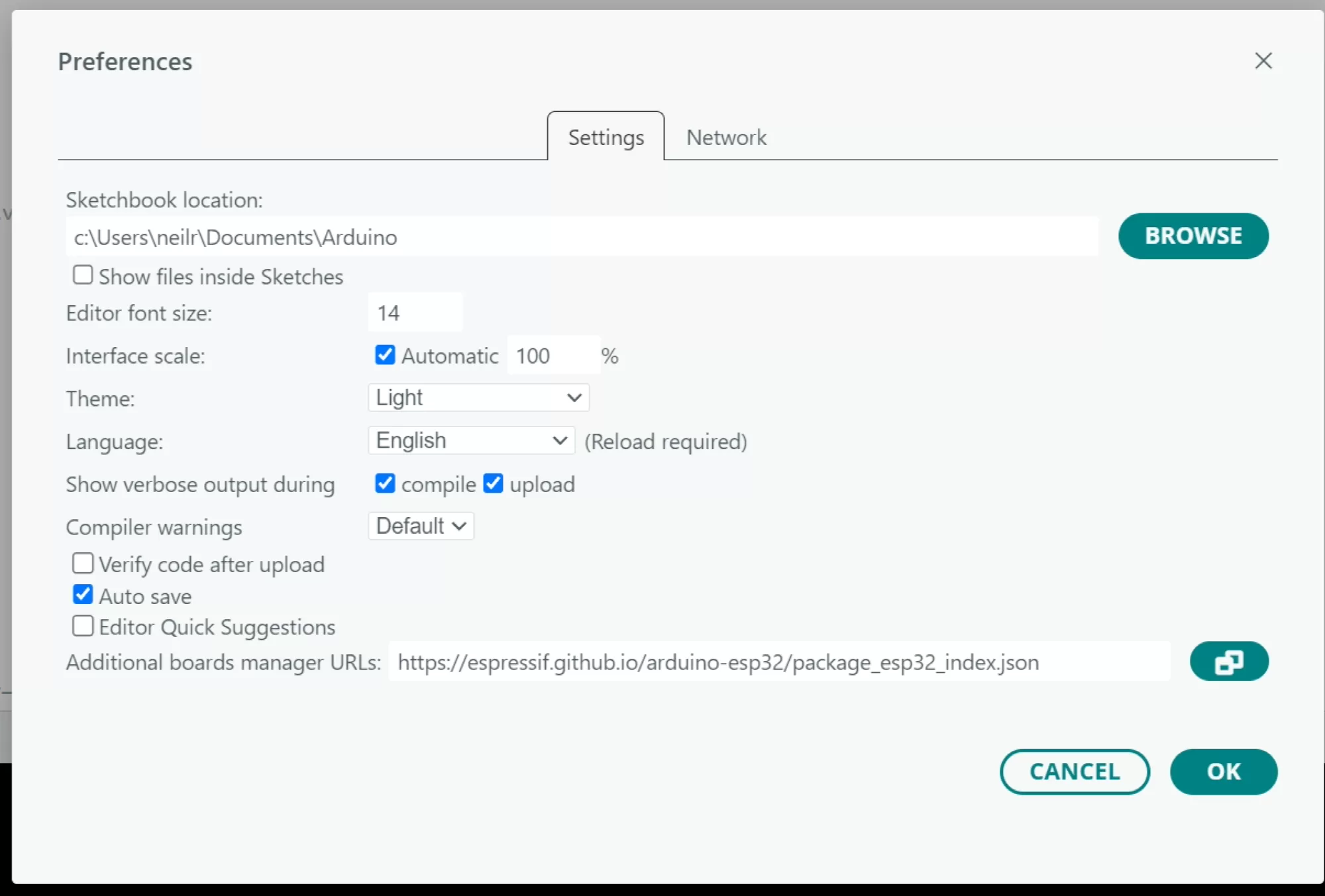
Figure 3 : Le champ des URL additionnelles du gestionnaire de cartes dans Préférences
Important pour les utilisateurs de C6 : La prise en charge d'ESP32-C6 n'existe que dans la version du noyau 3.0.0 et ultérieures. Si vous exécutez un ancien noyau 2.x, le C6 n'apparaîtra pas du tout dans la liste des cartes. Le S2 et S3 sont soutenus dans les deux, mais il n'y a aucune bonne raison de rester sur 2.x maintenant.
Étape 3 : Pilotes USB, ou l'absence de ceux-ci
Que vous ayez besoin d'un pilote dépend entièrement de la façon dont la carte se connecte à votre ordinateur, pas du chip utilisé.
Cartes avec USB natif
Les S2, S3 et C6 ont tous un périphérique USB intégré dans le silicium. Si la prise USB de votre carte va directement au chip, aucun pilote n'est nécessaire sur Windows 10 ou 11, macOS ou toute distribution Linux actuelle. La carte apparaît sous la forme d'un appareil série standard d'elle-même.
Cartes avec un pont USB vers série
De nombreuses cartes de développement installent un chip pont séparé pour que les téléchargements fonctionnent de la manière traditionnelle. Si votre carte en a un, installez le pilote correspondant :
- CP2102 ou CP2102N : le pilote Silicon Labs CP210x VCP.
- CH340 ou CH9102 : le pilote WCH.
- FTDI : le pilote FTDI VCP, bien que Windows le fournisse habituellement déjà.
Certaines cartes S3 ont deux prises USB, l'une câblée au pont et l'autre au chip. Elles se comportent différemment et produisent des noms de port différents. Notez la prise que vous avez utilisée, car cela importe lorsque vous accédez aux paramètres de la carte.
Permissions Linux
Sur Linux, le port existera mais vous ne pourrez pas l'ouvrir jusqu'à ce que votre utilisateur soit dans le groupe dialout :
sudo usermod -a -G dialout $USER
Déconnectez-vous et reconnectez-vous pour que cela prenne effet. Sur certaines distributions, le groupe s'appelle uucp à la place.
Étape 4 : Sélectionner votre carte
Allez sur Outils > Carte > esp32 et vous serez présenté avec une liste très longue. Si votre carte a une entrée spécifique par nom, utilisez-la, car le fabricant a déjà défini la taille de la mémoire flash, la PSRAM et les définitions de broches pour vous. Si ce n'est pas le cas, utilisez l'entrée du module de développement générique :
- ESP32-S2 : Module de développement ESP32S2
- ESP32-S3 : Module de développement ESP32S3
- ESP32-C6 : Module de développement ESP32C6
La liste est assez longue pour que le défilement soit pénible. Dans Arduino IDE 2, vous pouvez utiliser la liste déroulante du sélecteur de carte en haut de la fenêtre et taper dedans à la place, ce qui est bien plus rapide.
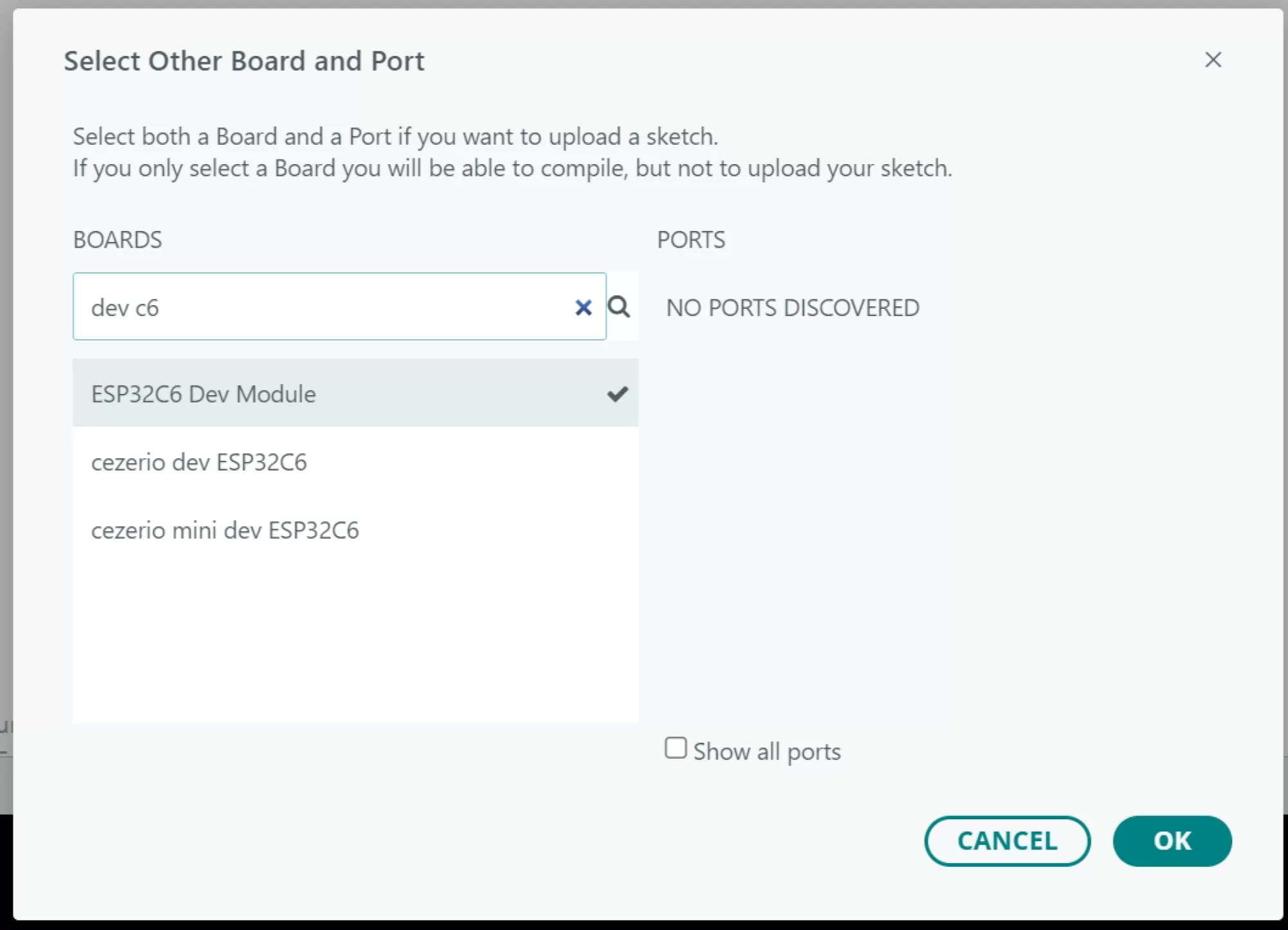
Figure 4 : Choisir le module de développement correct
Étape 5 : Les options de la carte qui importent vraiment
Une fois qu'une carte est sélectionnée, le menu Outils se remplit d'options. La plupart d'entre elles peuvent être laissées seules. Ce sont celles qui vous causeront des ennuis si elles sont erronées.
| Paramètre | ESP32-S2 | ESP32-S3 | ESP32-C6 |
|---|---|---|---|
| USB CDC au démarrage | Activé | Activé | Activé |
| Mode USB | Non proposé | CDC matériel et JTAG | Non proposé |
| Taille de la mémoire flash | Correspond au module | Correspond au module | Correspond au module |
| PSRAM | Activé seulement s'il est installé | QSPI ou OPI, selon ce qui est installé | Non supporté |
| Fréquence du processeur | 240 MHz | 240 MHz | 160 MHz |
| Schéma de partition | Par défaut au démarrage | Par défaut au démarrage | Par défaut au démarrage |
| Vitesse de téléchargement | 921600, réduisez en cas de manque de fiabilité | 921600, réduisez en cas de manque de fiabilité | 921600, réduisez en cas de manque de fiabilité |
| Niveau de débogage du noyau | Aucun | Aucun | Aucun |
USB CDC au démarrage
C'est la cause la plus commune de « mon sketch se télécharge mais le moniteur série ne montre rien ». Sur une carte utilisant l'USB natif, le port série auquel vous parlez est créé par le sketch lui-même. Si USB CDC au démarrage est désactivé, Serial est acheminé vers les broches UART matérielles à la place de la prise USB, et vous ne verrez rien du tout à l'écran. Réglez-le sur Activé.
Si votre carte utilise un chip pont USB vers série séparé, laissez-le désactivé, car dans ce cas, Serial allant aux broches UART est exactement ce que vous voulez.
Taille de la mémoire flash et schéma de partition
Réglez la taille de la mémoire flash pour correspondre au module, pas à la plus grande valeur de la liste. Si vous dites à l'IDE que vous avez 16MB et que le module n'en a que 4MB, le téléchargement peut sembler réussir puis la carte boucle ou perd ses paramètres stockés.
Le schéma de partition par défaut est correct jusqu'à ce que votre sketch compilé dépasse la partition d'application. Lorsque l'IDE commence à se plaindre que le sketch est trop volumineux, passez à l'un des schémas d'application plus volumineux. Si vous avez l'intention de faire des mises à jour en vol, vous avez besoin d'un schéma avec deux partitions d'application, car OTA écrit la nouvelle image dans la partition de secours avant de basculer.
PSRAM
Activez PSRAM uniquement si le module en a physiquement. L'activer sur un module qui n'en a pas produira des défaillances au démarrage ou un flot d'erreurs sur la sortie série. Sur le S3, vous devez aussi choisir entre QSPI et OPI, et l'obtenir mal cause les mêmes symptômes. Vérifiez le numéro de pièce du module si vous n'êtes pas sûr. Le C6 n'a pas du tout de support PSRAM, donc l'option n'apparaît pas.
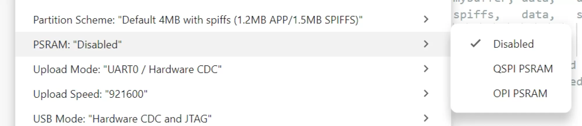
Figure 5 : Les options de la carte sous le menu Outils
Étape 6 : Trouver le port
Branchez la carte et regardez sous Outils > Port. Sous Windows, vous obtiendrez un numéro COM. Sur macOS, vous verrez quelque chose commençant par /dev/cu.usbmodem pour l'USB natif ou /dev/cu.usbserial pour un chip pont. Sur Linux, ce sera /dev/ttyACM0 ou /dev/ttyUSB0.
Si rien n'apparaît, travaillez dans cet ordre :
- Essayez un câble différent. Cela résout le problème plus souvent que n'importe quoi d'autre.
- Essayez une prise USB différente, de préférence directement sur la machine plutôt que par un concentrateur.
- Vérifiez si la carte a un chip pont qui a besoin d'un pilote.
- Sous Windows, ouvrez le Gestionnaire de périphériques et cherchez un périphérique inconnu qui apparaît et disparaît au fur et à mesure que vous branchez la carte.
Il y a un comportement avec l'USB natif qui surprend tout le monde la première fois. Le port appartient au sketch en cours d'exécution, il disparaît donc au redémarrage et réapparaît une ou deux secondes plus tard. Si vous téléchargez un sketch qui plante tôt, le port peut disparaître définitivement jusqu'à ce que vous forciez la carte en mode téléchargement.
Étape 7 : Forcer le mode téléchargement
Si le téléchargement échoue avec un message sur l'échec de la connexion, vous devez mettre le chip dans son bootloader manuellement. La séquence est toujours la même :
- Maintenez enfoncé le bouton BOOT (parfois marqué IO0).
- Appuyez sur et relâchez le bouton RESET (parfois marqué EN ou RST).
- Relâchez BOOT.
La carte est maintenant dans son bootloader ROM, en attente. Sur une carte USB natif, elle énumèrera comme un port série différent à ce moment, alors revenez dans Outils > Port et sélectionnez le nouveau avant de télécharger. Une fois le téléchargement terminé, appuyez sur RESET seul pour exécuter le sketch, et le port d'origine reviendra.
Notes par chip
S2 : le plus susceptible des trois d'avoir besoin de la séquence manuelle de boutons. Prenez l'habitude de le faire de manière systématique et vous vous épargnerez beaucoup de tracas.
S3 : se redéfinit habituellement en mode téléchargement automatiquement via USB natif, mais pas toujours, particulièrement si le sketch précédent a désactivé l'USB ou a échoué lors de la configuration.
C6 : généralement bien comporté. S'il refuse, la même séquence de boutons s'applique.
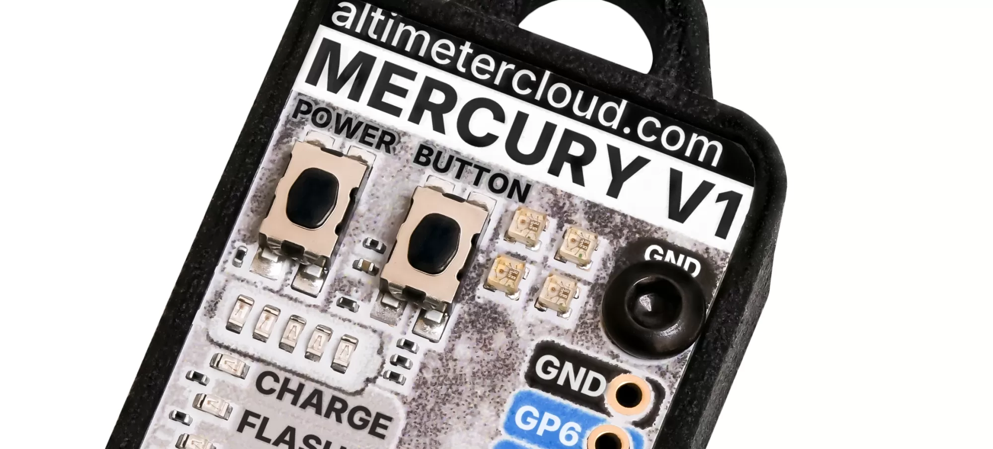
Figure 6 : Boutons BOOT et RESET - Sur la mercure le bouton POWER est RESET, et le BOUTON est le bouton BOOT par exemple.
Étape 8 : Un premier sketch pour prouver la chaîne d'outils
Résistez à l'envie de commencer par blink. Sur de nombreuses cartes de développement S3 et C6, la LED embarquée est un type RVB adressable plutôt qu'une simple, donc un sketch blink standard ne fait rien du tout et vous vous demandez si le téléchargement a fonctionné. Imprimez plutôt quelque chose via série, car cela vous dit que le chip exécute vraiment votre code et confirme les paramètres de la carte en même temps.
void setup() {
  Serial.begin(115200);
  delay(2000);   // laisse le port série USB s'énumérer avant d'imprimer

  Serial.println();
  Serial.println("ESP32 est vivant");
  Serial.print("Modèle de chip  : ");
  Serial.println(ESP.getChipModel());
  Serial.print("Noyaux       : ");
  Serial.println(ESP.getChipCores());
  Serial.print("Octets flash : ");
  Serial.println(ESP.getFlashChipSize());
  Serial.print("Mémoire libre   : ");
  Serial.println(ESP.getFreeHeap());
}

void loop() {
  Serial.print("temps de fonctionnement ms: ");
  Serial.println(millis());
  delay(1000);
}
Cliquez sur la flèche pour télécharger, puis ouvrez le Moniteur série avec l'icône loupe en haut à droite et réglez le débit en bauds sur 115200. Vous devriez voir le chip se signaler. Si la ligne du modèle dit ESP32-S3 et que vous avez sélectionné une carte S3, tout de l'IDE jusqu'au silicium communique correctement.
Le délai de deux secondes au démarrage est intentionnel. Avec l'USB natif, l'hôte prend un moment pour ouvrir le port après la réinitialisation, et tout ce qui est imprimé avant cela est perdu. Ne le remplacez pas par une simple boucle while (!Serial);, car sur une carte fonctionnant sur batterie sans ordinateur connecté, cela se bloquera indéfiniment. Si vous voulez attendre correctement, mettez un délai d'expiration :
while (!Serial && millis() < 3000) {
  delay(10);
}
Étape 9 : Installation des bibliothèques
La plupart des capteurs et périphériques ont besoin d'une bibliothèque. Utilisez le gestionnaire de bibliothèques, qui est l'icône des livres dans la barre d'outils de gauche, ou Sketch > Inclure une bibliothèque > Gérer les bibliothèques. Cherchez, choisissez, installez, et l'IDE proposera également de ramener les dépendances. Dites oui à celles-là.
Pour une bibliothèque fournie sous forme de fichier ZIP, utilisez Sketch > Inclure une bibliothèque > Ajouter une bibliothèque .ZIP. Elle est décompressée dans le dossier des bibliothèques à l'intérieur de votre sketchbook, et vous pouvez aussi simplement y glisser un dossier à la main si vous préférez. Redémarrez l'IDE après si une bibliothèque ajoutée manuellement n'apparaît pas.
Une chose à surveiller : pas toutes les bibliothèques Arduino fonctionnent sur l'ESP32, et parmi celles qui le font, pas toutes fonctionnent sur les trois chips. Tout ce qui poke les registres AVR directement, ou suppose l'ancien ensemble de périphériques ESP32 classique, peut échouer à compiler sur le C6 en particulier car c'est un composant RISC-V plutôt qu'Xtensa. Si une bibliothèque refuse de compiler, vérifiez son suivi des problèmes avant de supposer que votre configuration est cassée.
Gardez vos versions sous contrôle
Cette partie est ignorée par presque tout le monde et cause ensuite des problèmes six mois plus tard. La version du noyau contre laquelle vous compilez affecte le chronométrage, le comportement du périphérique et occasionnellement le sens d'un appel API. Un projet qui s'est construit et exécuté parfaitement la saison dernière peut se comporter différemment après une mise à jour.
Deux habitudes valent la peine d'être acquises :
- Notez la version du noyau et les versions des bibliothèques que vous avez utilisées, aux côtés du code. Un commentaire en haut du fichier sketch principal suffit.
- Ne mettez pas à jour le noyau au milieu d'un projet à moins d'avoir une raison. Finissez, vérifiez, puis mettez à jour, puis re-vérifiez avant de vous y fier à nouveau.
Le gestionnaire de cartes vous laisse choisir n'importe quelle version publiée dans la liste déroulante, pas seulement la plus récente, donc revenir en arrière est simple si une mise à jour casse quelque chose.
Dépannage
| Symptôme | Cause probable et correction |
|---|---|
| Aucun port n'apparaît du tout | Câble de charge uniquement, pilote pont manquant, ou un concentrateur en travers. Essayez d'abord un câble connu pour fonctionner. |
| Échec de la connexion, ou expiration du délai en attente d'en-tête de paquet | Le chip n'est pas en mode téléchargement. Utilisez la séquence BOOT et RESET, puis re-sélectionnez le port qui apparaît. |
| Le téléchargement réussit mais le moniteur série est vide | USB CDC au démarrage est désactivé, ou le débit en bauds est erroné, ou vous avez imprimé avant que le port soit ouvert. |
| Redémarrages continus avec une raison de redémarrage imprimée à 115200 | Habituellement PSRAM activé alors qu'il n'y en a pas, le mauvais mode PSRAM sur un S3, ou une taille de flash erronée. |
| Détecteur de baisse de tension déclenché | Courant d'alimentation insuffisant, souvent pendant la transmission Wi-Fi. Utilisez une meilleure alimentation ou un câble plus court. |
| Sketch trop volumineux | Changez vers un schéma de partition avec une zone d'application plus grande. |
| Le port disparaît au moment où le sketch démarre | Le sketch plante lors de la configuration. Forcez le mode téléchargement et téléchargez quelque chose de connu pour fonctionner. |
| Seul le Nano ESP32 s'affiche dans la liste des cartes | Vous avez installé Arduino ESP32 Boards plutôt que esp32 par Espressif Systems. Installez également le package Espressif. |
| La carte n'apparaît pas dans la liste | Noyau trop ancien, particulièrement pour le C6. Mettez à jour à la version 3.x ou ultérieure. |
| Erreurs de compilation immédiatement après l'installation du noyau | Téléchargement interrompu. Supprimez le package esp32 dans le gestionnaire de cartes et réinstallez-le. |
Où aller ensuite
Une fois que vous avez la sortie série qui fonctionne, la partie difficile est derrière vous. Tout ce qui suit est juste du code. Les exemples qui viennent avec le noyau sont un bon point de départ, et ils sont tous sous Fichier > Exemples une fois qu'une carte ESP32 est sélectionnée. Seuls les exemples pertinents pour le chip que vous avez choisi seront affichés, ce qui est utile en soi lorsque vous essayez de comprendre ce qu'une partie particulière peut faire.
Si quelque chose dans ce guide ne correspond pas à ce que vous voyez, les paramètres de la carte sont le premier endroit à regarder. Neuf fois sur dix, c'est USB CDC au démarrage, la taille de la flash, ou le paramètre PSRAM.