Altimeter code: Page 1, introduction to DIY rocket altimeters
Welcome to our free step by step tutorial on how to build your own DIY model rocket altimeter. Over five pages you will learn to write altimeter code in the Arduino IDE for an ESP32, read a barometric pressure sensor, work out your height above the launch pad, detect a launch, record apogee, log flight data at 50 samples a second, and download your flights over WiFi. Everything here is beginner friendly model rocketry electronics: no prior programming experience is needed, and every project is a single sketch you copy and paste.
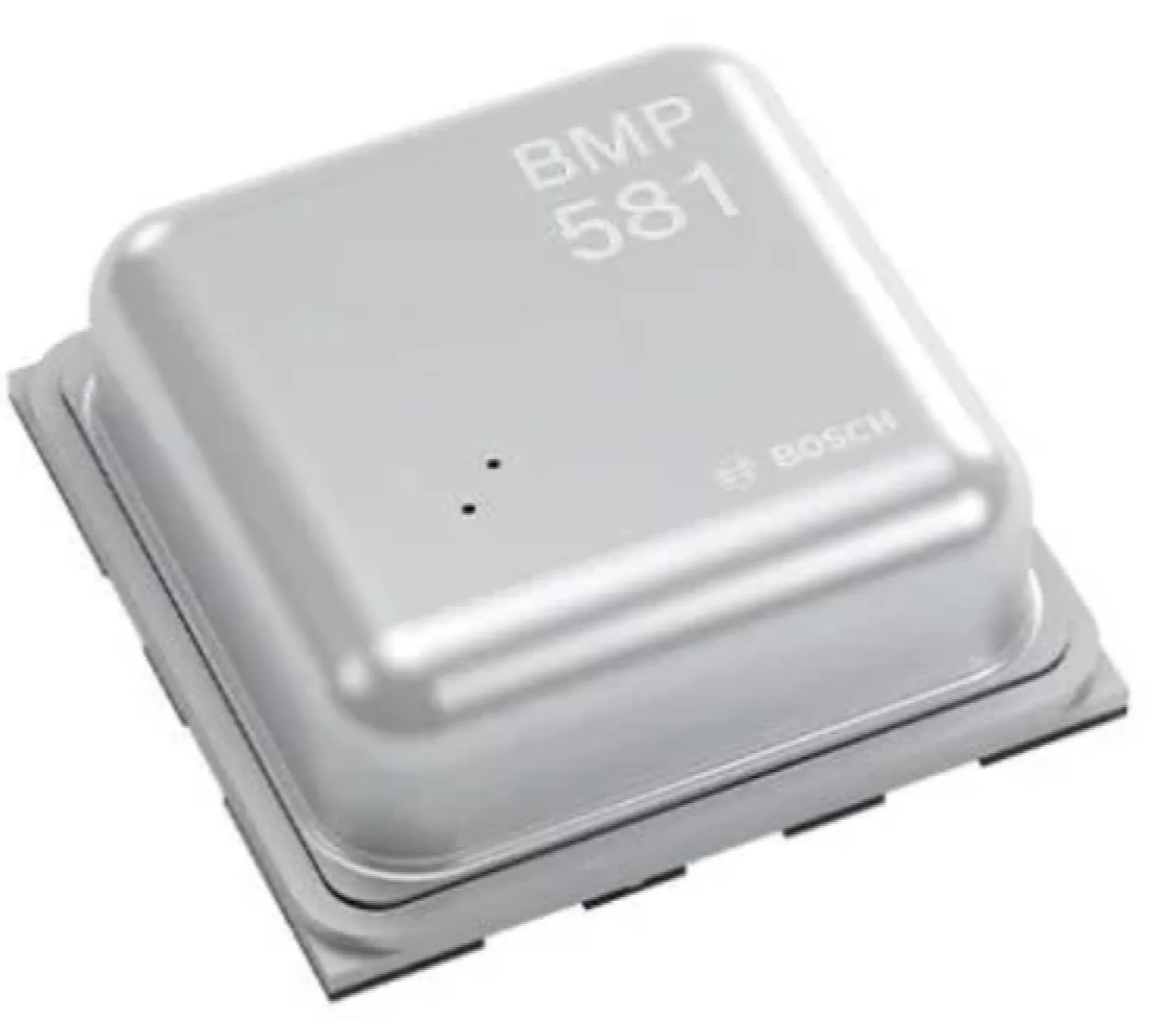 The projects are written for our Mercury V1 rocket altimeter, which is the one altimeter we sell with the flash left unlocked on purpose so you can use it as an ESP32-C6 development board. They will also run on any ESP32 with a Bosch BMP581 or BMP390 pressure sensor wired to it, so if you would rather build a homemade altimeter from breakout boards you can follow along exactly the same way.
You do not need to be a programmer for any of this. If you can copy some text into a window and press a button, you can build all four.
- Part 1, this one. Get set up and read the pressure sensor.
- Part 2. A simple apogee altimeter that remembers your last ten flights.
- Part 3. A logging altimeter that gives you a flight as a spreadsheet.
- Part 4. The same thing, but it makes its own WiFi network so you can download flights from your phone.
- Part 5. Add the accelerometer and gyroscope to the log.
There is a section at the end of this page on running these projects on your own hardware. If you already own the parts, nothing here asks you to buy anything from us.
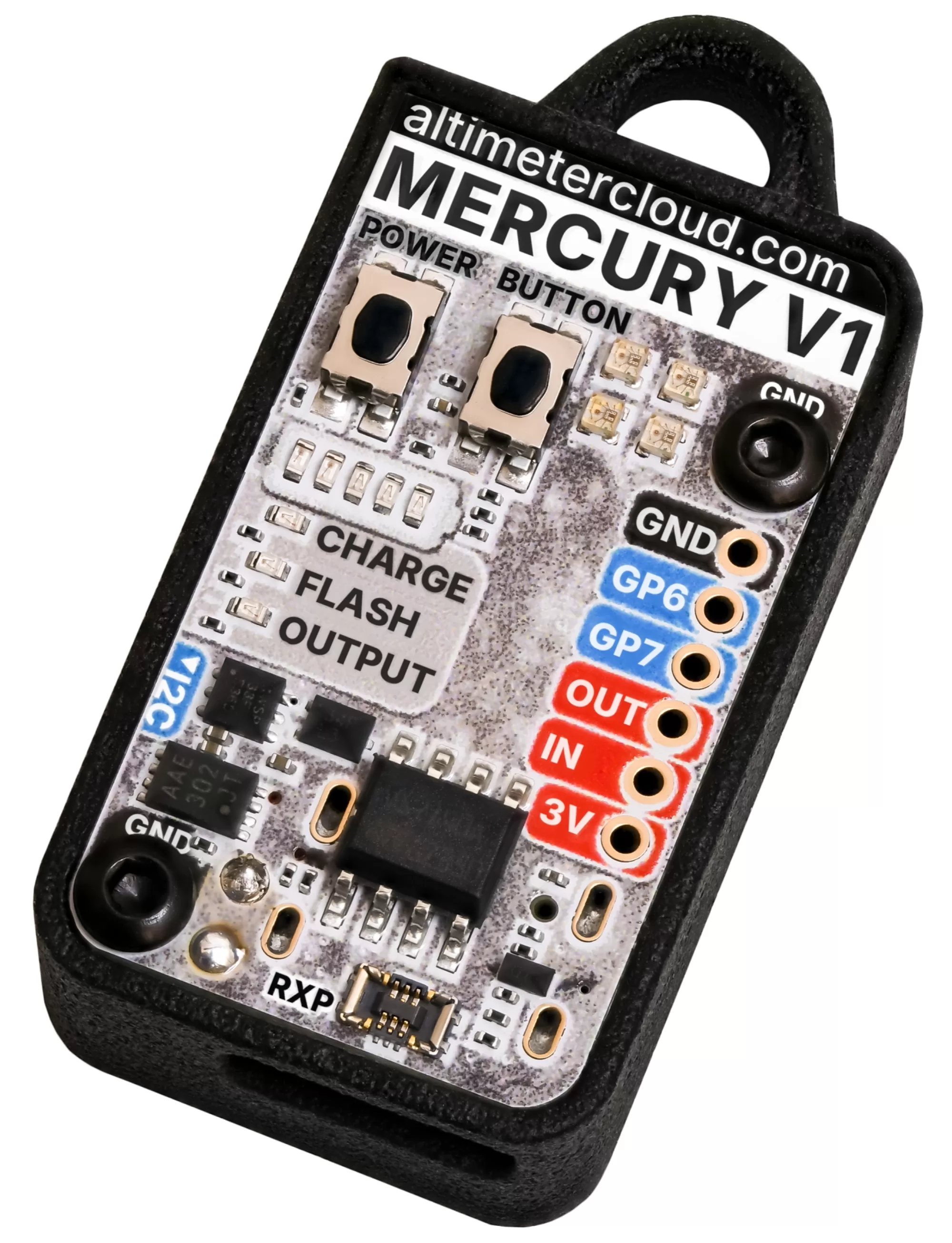 What you need
- A Mercury V1, or your own ESP32 with a BMP390 or BMP581 breakout.
- A USB-C cable that carries data. Charge only cables are the most common reason a board never shows up, and they look identical.
- A computer with the Arduino IDE on it.
- About half an hour.
The Mercury V1 is stocked by hobby shops and online retailers in the UK, Europe and further afield, and our stockists page will point you at the nearest one. It is the only altimeter we make that we leave open for you to program, so it is the one to get if you want to work through this series and still have a proper flight computer at the end of it.
Step 1: Get the Arduino IDE ready
If you have never used the Arduino IDE with an ESP32 before, start with our setup guide. It walks through installing the IDE, adding ESP32 support, and the few settings that catch everybody out. Come back here when you have uploaded its test sketch and seen something appear in the Serial Monitor.
Already know your way around? Install the esp32 package by Espressif Systems, version 3.x or later. The Mercury uses the chip's own USB, so there is no driver to install.
Step 2: Know that you cannot break it
This is the bit that stops most people trying, so let us deal with it first. Putting your own code on a Mercury is not permanent and not risky. Our firmware updater will put the original firmware back whenever you want it, from any state, including a board you have completely overwritten.
When you go back, choose full install, not update. An update only replaces the program and assumes our original flash layout is still there. After your own sketches it will not be. A full install rewrites everything and always works.
Two things to do before you start: upload any flights still sitting on the device, and make a note of your settings, because both go when you flash your own code. Your Altimeter Cloud account knows the device by a serial number built into the chip, so nothing there is lost and it will reappear as itself afterwards.
Step 3: Board settings
Choose the board
Go to Tools, Board, esp32 and pick ESP32C6 Dev Module from the list. The list is enormous, so it is quicker to use the board selector at the top of the window and type "C6" into it.
There is no Mercury entry and there does not need to be one. The Mercury is built around an ESP32-C6, so the generic C6 development module entry is exactly right. If you cannot find it at all, your ESP32 package is too old: C6 support only arrived in version 3.0, so update it in the Boards Manager.
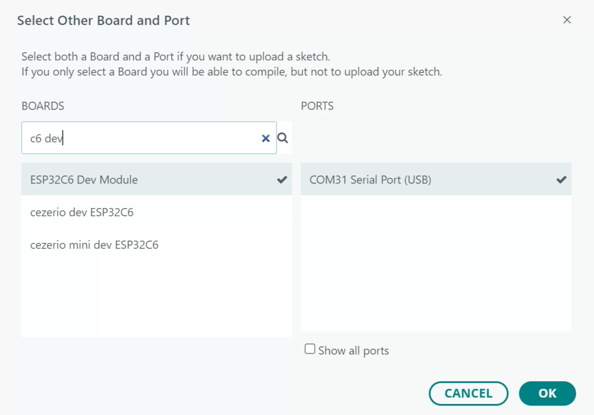
Click the drop down at the top and "Select other board and port..."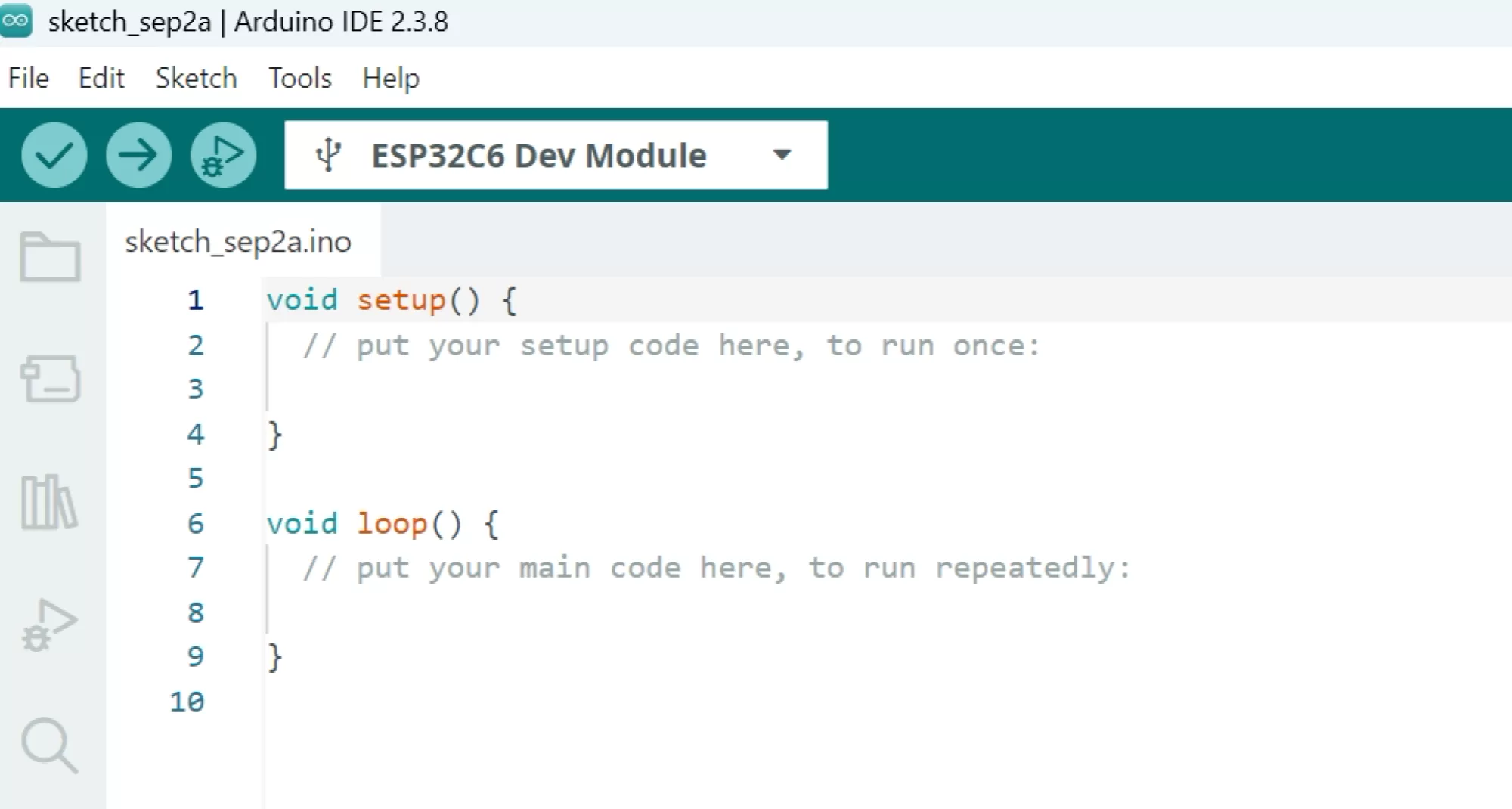
ESP32C6 Dev Module board type selected at the top
Then set these
| Setting | Value |
| USB CDC On Boot | Enabled |
| Flash Size | 4MB (32Mb) |
| Partition Scheme | Default 4MB with spiffs |
| CPU Frequency | 160MHz |
| Erase All Flash Before Sketch Upload | Enabled for now |
| Upload Speed | 921600 |
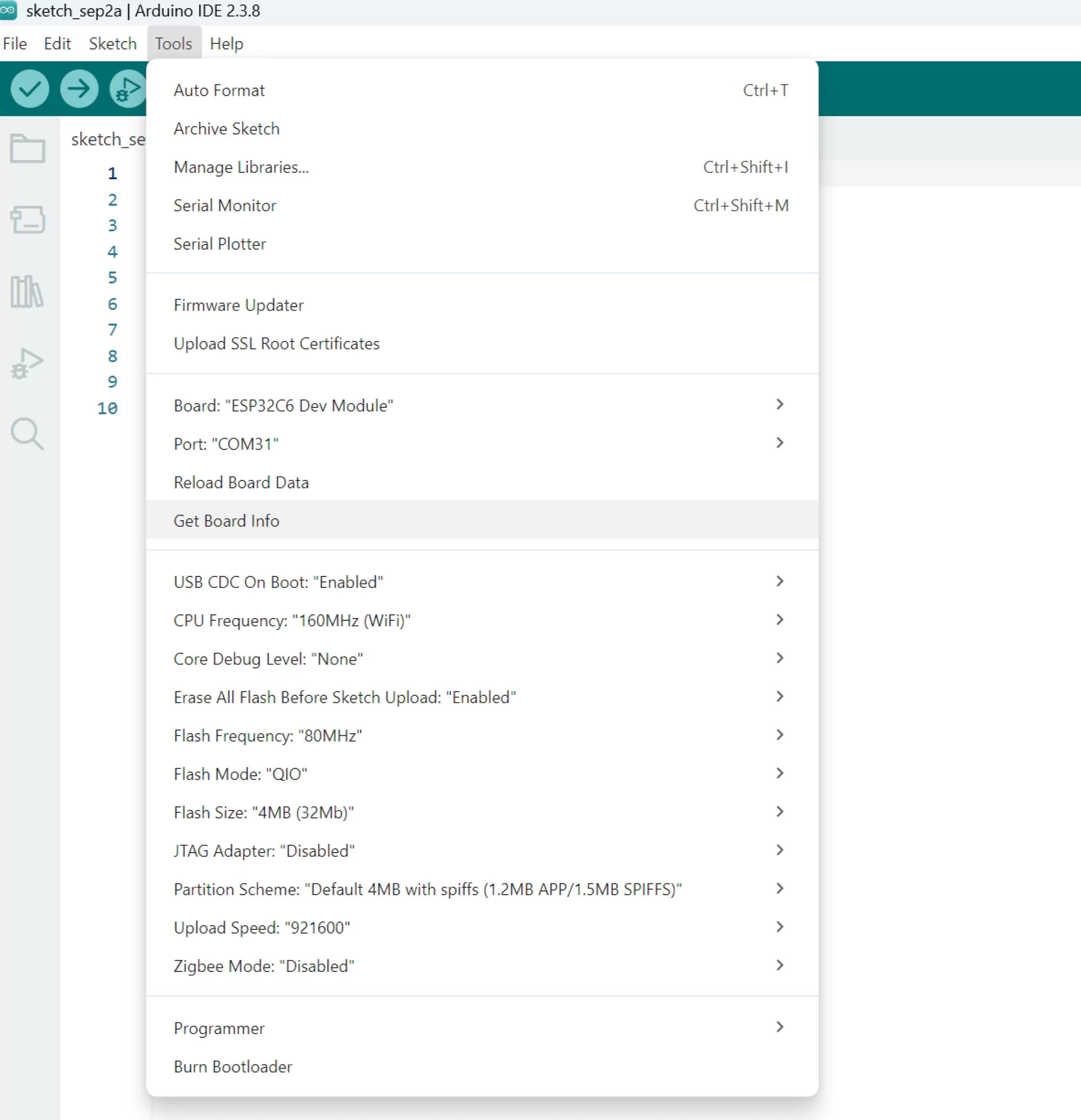
Make sure you set the tools menu options like this
Two of those are worth a separate mention.
USB CDC On Boot has to be enabled or the Serial Monitor stays blank forever. It is the single most common thing to get wrong.
Erase All Flash should be enabled for your first upload. Our firmware divides the flash up differently to a standard Arduino sketch, and erasing clears out the old layout so nothing left over from it can confuse things. Once that first upload has worked you can set it back to disabled, which makes every upload after that a good deal quicker.
Two Mercury quirks worth knowing before your first upload
Getting it to accept the upload. ESP32 boards have to be in boot mode before they will take new code, and they usually drop into it on their own. If yours does not, and the IDE sits there saying it failed to connect, do it by hand:
- Hold down BUTTON, which is the BOOT button.
- Tap POWER, which is the RESET button, and let go of it.
- Let go of BUTTON.
The board is now waiting for code. It shows up as a different port while it sits there, so go back to Tools, Port and select the new one before you press upload. Once the upload has finished, the original port comes back.
Getting it to run the code afterwards. An upload does not always leave a Mercury running. Quite often the IDE will say it uploaded perfectly and the board will just sit there doing nothing at all, particularly if you put it into boot mode by hand. Nothing has gone wrong. Tap POWER and it will restart and run your new sketch. Get into the habit of tapping it after every upload and you will save yourself a lot of head scratching.
Step 4: Install three libraries
Open the Library Manager, the books icon down the left hand side, and install these three. Say yes if it offers to install anything they depend on.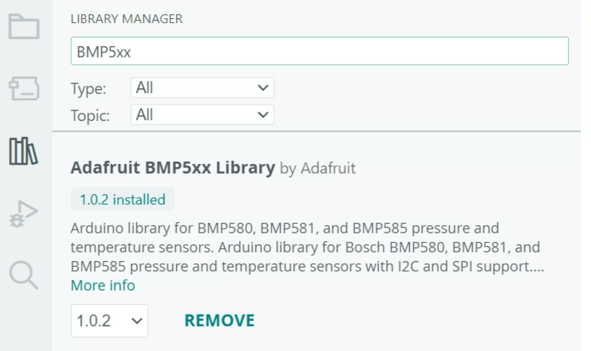
| Search for | By | What it does |
| Adafruit NeoPixel | Adafruit | Drives the status LED |
| Adafruit BMP5xx Library | Adafruit | The BMP581 pressure sensor on newer boards |
| BMP388_DEV | Martin Lindupp | The BMP390 pressure sensor on older boards |
Install both pressure sensor libraries even though your board only has one of the two sensors. It saves you finding out which is under the metal shield, and the spare one only takes up a few kilobytes.
What is on the board
Everything is on a pin, and every sketch in this series starts with the same short list of them so you can see at a glance what is connected where.
| Pin | What it is |
| GPIO21 and GPIO22 | I2C, the two wire bus the sensors talk on |
| GPIO20 | Powers the pressure sensor and the accelerometer |
| GPIO3 | Powers the status LED |
| GPIO2 | Status LED data |
| GPIO5 | The output that fires an ejection charge |
| GPIO1 | Goes HIGH when a charging cable is plugged in |
| GPIO0 | Reads half the battery voltage |
| GPIO18 | Ground for the battery reading. Has to be driven LOW |
| GPIO9 | The BUTTON on the case |
Three things to know
1. Good practice: set GPIO5 low, first thing, every time. That pin fires the ejection charge in a real rocket. A pin your code has not set up yet is left floating, and floating is not quite the same as off. It costs two lines at the top of setup and it is a habit worth having, so every sketch in this series does it and yours should too.
2. The sensors and the LED have their own power pins. GPIO20 and GPIO3 have to be HIGH or neither will respond to anything. This is how the Mercury gets its standby current down to almost nothing, and it is also why a sketch that forgets them looks like a board with no sensors on it.
3. Your sketch will never go to sleep. Our firmware nods off between readings and shuts down when a flight is over. Yours does not, so a Mercury running your code will flatten its battery in a few hours. For now, just plug it in to charge when you are finished with it. Sleep, and the rather large difference it makes to battery life, gets a page of its own at the end of the series.
Step 5: Your first sketch
This one reads the pressure sensor and prints what it sees. It does not save anything or change anything on the board. It is worth running before the later projects, because once you have seen it work you know the board and the software are both fine, and anything odd later is in the new code rather than the setup.
Every sketch in this series is laid out the same way: the pins at the top, then setup() which runs once, then loop() which runs over and over, and then the smaller functions those two use. Read the top half and you will understand what the altimeter does. Read the bottom half when you want to know how.
One thing to point out before you read it. Both pressure sensor libraries will happily hand you an altitude if you ask for one, and we never do. The sketch asks them for pressure and temperature only, and does the height sum itself in a function at the bottom called heightAbove(). That is deliberate. Different libraries use slightly different constants and make different assumptions about sea level, so the same pressure can come out as two different heights depending on whose code you used. Doing the sum ourselves means every one of our altimeters, every version of our firmware and every project in this series turn the same pressure into the same height. There is more on that formula later in the series.
In the Arduino IDE, File, New Sketch. Select everything in the window, delete it, and paste this in. Then press the arrow to upload.
/*
  01_pressure_sensor.ino

  Mercury altimeter project 1: reading the pressure sensor

  Part of the Altimeter Cloud "Build your own altimeter" series.
  https://www.altimetercloud.com/de/rocketry-news/

  Prints pressure, temperature and height five times a second, and colours the
  status LED by height: green where you started, blue as it goes up, red as it
  comes down. Lift the board off the desk and watch it change.

  Nothing is saved and nothing on the board is altered.

  Libraries needed (Arduino Library Manager):
    Adafruit NeoPixel        by Adafruit
    Adafruit BMP5xx Library  by Adafruit
    BMP388_DEV               by Martin Lindupp

  Board settings: ESP32C6 Dev Module, USB CDC On Boot ENABLED, Flash Size 4MB,
  Partition Scheme "Default 4MB with spiffs", CPU 160MHz.
*/

#include <Wire.h>
#include <Adafruit_NeoPixel.h>
#include <Adafruit_BMP5xx.h>
#include <BMP388_DEV.h>

// ------------------------------------------------------------------
// The Mercury V1 pins. These are the same on every board.
// Using your own ESP32? Change these to the pins you wired.
// ------------------------------------------------------------------
#define LED_POWER      3    // Powers the status LED. Must be HIGH
#define LED_DATA       2    // Status LED data line
#define SENSOR_POWER  20    // Powers the pressure sensor and IMU. Must be HIGH
#define I2C_SDA       21    // I2C data
#define I2C_SCL       22    // I2C clock
#define OUTPUT_PIN     5    // Ejection charge output. Keep it LOW
#define BUTTON         9    // The BUTTON on the case. LOW when pressed
#define USB_DETECT     1    // HIGH when a charging cable is plugged in
#define BATTERY        0    // Reads half the battery voltage
#define BATTERY_GND   18    // Ground for the battery divider. Must be LOW

#define LED_BRIGHTNESS 4    // Colours are divided by this. 1 is dazzling

// ------------------------------------------------------------------

Adafruit_NeoPixel led(4, LED_DATA, NEO_GRB + NEO_KHZ800);
Adafruit_BMP5xx bmp581;
BMP388_DEV      bmp390(Wire);

bool  have_bmp581 = false;
bool  have_bmp390 = false;

float pressure_hpa  = 0;    // Latest pressure reading
float temperature_c = 0;    // Latest temperature reading
float reference_hpa = 0;    // The pressure we are calling zero metres

unsigned long next_reading = 0;


void setup() {
  Serial.begin(115200);

  // Always do this first. The output pin fires the ejection charge on a
  // flying altimeter, and a pin nobody has set up yet is left floating.
  pinMode(OUTPUT_PIN, OUTPUT);
  digitalWrite(OUTPUT_PIN, LOW);

  // The LED and the sensors each have their own power pin. Until these go
  // HIGH neither of them will do anything at all.
  pinMode(LED_POWER, OUTPUT);
  digitalWrite(LED_POWER, HIGH);
  pinMode(SENSOR_POWER, OUTPUT);
  digitalWrite(SENSOR_POWER, HIGH);

  pinMode(BATTERY_GND, OUTPUT);
  digitalWrite(BATTERY_GND, LOW);
  pinMode(USB_DETECT, INPUT);
  pinMode(BUTTON, INPUT_PULLUP);

  led.begin();
  setLed(255, 0, 0);          // red while we start up

  Wire.begin(I2C_SDA, I2C_SCL, 400000);
  delay(100);                 // give the sensors a moment to wake up

  // Wait for the Serial Monitor, but not forever, because on a battery there
  // is nobody there to wait for.
  unsigned long start = millis();
  while (!Serial && millis() - start < 2500) delay(10);
  delay(250);

  Serial.println();
  Serial.println("Mercury altimeter project 1");
  startPressureSensor();

  Serial.print("Battery: ");
  Serial.print(analogReadMilliVolts(BATTERY) * 2 / 1000.0, 2);
  Serial.println(" V");

  // Average twenty readings and call that zero metres.
  setLed(255, 200, 0);        // yellow while we measure the reference
  delay(300);
  float total = 0;
  for (int i = 0; i < 20; i++) {
    readSensor();
    total = total + pressure_hpa;
    delay(25);
  }
  reference_hpa = total / 20;

  Serial.print("Reference pressure: ");
  Serial.print(reference_hpa, 2);
  Serial.println(" hPa, which is now zero metres");
  Serial.println();
  Serial.println("time_s,pressure_hPa,temp_C,height_m");

  setLed(0, 255, 0);          // green, ready
}


void loop() {
  // Take a reading every 200 milliseconds, which is five a second.
  if (millis() < next_reading) return;
  next_reading = millis() + 200;

  if (!readSensor()) return;

  float height = heightAbove(reference_hpa, pressure_hpa, temperature_c);

  // Colour the LED by height. Green where we started, fading to blue as it
  // goes up and red as it comes down, full colour by two metres.
  int amount = abs(height) * 127;
  if (amount > 255) amount = 255;

  if (height > 0.1)       setLed(0, 255 - amount, amount);
  else if (height < -0.1) setLed(amount, 255 - amount, 0);
  else                    setLed(0, 255, 0);

  Serial.print(millis() / 1000.0, 2);
  Serial.print(",");
  Serial.print(pressure_hpa, 3);
  Serial.print(",");
  Serial.print(temperature_c, 2);
  Serial.print(",");
  Serial.println(height, 2);
}


// ==================================================================
// The functions setup() and loop() use. Have a read through when you
// are ready, they are short.
// ==================================================================


// Set the LED to a colour. Older boards have one pixel and newer ones have
// four, so we set all four and let any spare ones be ignored.
void setLed(int red, int green, int blue) {
  for (int i = 0; i < 4; i++) {
    led.setPixelColor(i, led.Color(red / LED_BRIGHTNESS,
                                   green / LED_BRIGHTNESS,
                                   blue / LED_BRIGHTNESS));
  }
  led.show();
}


// Is there a chip at this address on the I2C bus?
bool deviceAt(byte address) {
  Wire.beginTransmission(address);
  return Wire.endTransmission() == 0;
}


// Mercury boards carry one of two pressure sensors depending on how old they
// are, and the two live at different addresses, so we can just ask the bus
// which one is there.
//    BMP581 at 0x46 or 0x47      BMP390 at 0x76 or 0x77
void startPressureSensor() {
  if (deviceAt(0x46) || deviceAt(0x47)) {
    Serial.println("Found a BMP581");
    bmp581.begin(BMP5XX_ALTERNATIVE_ADDRESS, &Wire) ||
    bmp581.begin(BMP5XX_DEFAULT_ADDRESS, &Wire);
    bmp581.setPressureOversampling(BMP5XX_OVERSAMPLING_8X);
    bmp581.setIIRFilterCoeff(BMP5XX_IIR_FILTER_COEFF_3);
    bmp581.setOutputDataRate(BMP5XX_ODR_80_HZ);
    bmp581.setPowerMode(BMP5XX_POWERMODE_NORMAL);
    bmp581.enablePressure(true);
    have_bmp581 = true;

  } else if (deviceAt(0x76) || deviceAt(0x77)) {
    Serial.println("Found a BMP390");
    bmp390.begin(NORMAL_MODE, OVERSAMPLING_X8, OVERSAMPLING_X2,
                 IIR_FILTER_4, TIME_STANDBY_20MS);
    bmp390.startNormalConversion();
    have_bmp390 = true;

  } else {
    Serial.println("No pressure sensor found!");
  }
}


// Take a reading. Updates pressure_hpa and temperature_c.
// We only ever ask the library for pressure and temperature. The height sum
// below is ours, so that every one of our devices and every version of our
// firmware gives you the same answer from the same pressure.
bool readSensor() {
  if (have_bmp581) {
    if (!bmp581.performReading()) return false;
    pressure_hpa  = bmp581.pressure;
    temperature_c = bmp581.temperature;
    return true;
  }
  if (have_bmp390) {
    return bmp390.getTempPres(temperature_c, pressure_hpa);
  }
  return false;
}


// Turn a pressure into a height above wherever we took our reference.
// This is the same sum our own altimeters use.
float heightAbove(float reference, float hpa, float temp) {
  return ((temp + 273.15) / 0.0065) * (1.0 - pow(hpa / reference, 0.190266669));
}
Uploaded and nothing is happening? Tap the POWER button on the Mercury. Boards often need that nudge after an upload before they start running the new code.
What you should see
Open the Serial Monitor, the magnifying glass at the top right, and set it to 115200 baud. Within a couple of seconds you should get this: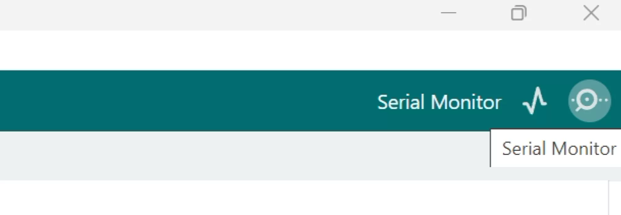
Click the icon on the top right of Arduino for the serial monitor
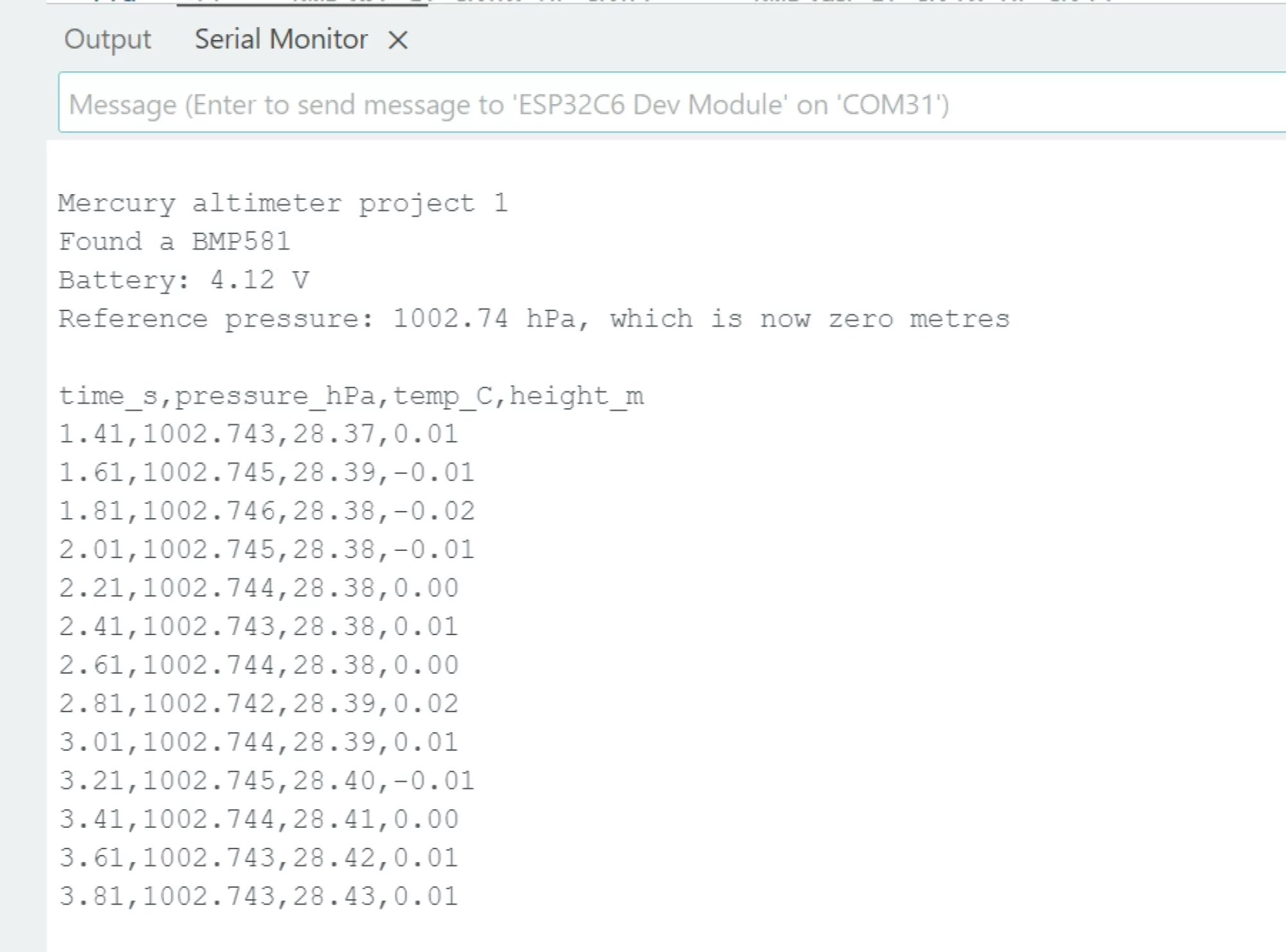
Mercury altimeter project 1
Found a BMP581
Battery: 4.02 V
Reference pressure: 1004.31 hPa, which is now zero metres

time_s,pressure_hPa,temp_C,height_m
2.41,1004.308,23.44,0.02
2.61,1004.315,23.44,-0.04
2.81,1004.302,23.45,0.07
3.01,1004.311,23.45,-0.01
The LED should be green. Now try these, in order, because each one shows you something different.
- Leave it alone for a minute. The height wanders by a few centimetres. That wobble is the noise in the sensor, and it is the smallest change any altimeter can honestly see.
- Lift it a metre off the desk and hold it there. You should see about a metre appear, and the LED turns blue and stays blue. Air pressure really does change that much over a metre, which is the whole reason this works.
- Breathe on it. The temperature climbs and the height jumps about. Not a fault. It is why a real altimeter needs a vent hole and why you never mount one next to something warm.
- Leave it running for ten minutes. The height drifts, probably a metre or two, because the weather is very slowly changing. That drift is exactly why the next project does not simply take one reading at switch on and call it the ground.
If something goes wrong
| What you see | What to do |
| Nothing in the Serial Monitor | USB CDC On Boot is probably Disabled. Set it to Enabled and upload again. |
| No pressure sensor found | Check both pressure sensor libraries installed, then check GPIO20 is being set HIGH. Nothing answers on the bus until it is. |
| The board will not take the upload | Put it in boot mode by hand: hold BUTTON, tap POWER, release BUTTON. Then pick the new port under Tools, Port and upload again. |
| It says it uploaded, but the board does nothing | Tap POWER to restart it. This is normal, especially after a manual boot mode upload. |
| ESP32C6 Dev Module is not in the board list | Your ESP32 package predates C6 support. Update it to 3.0 or later in the Boards Manager. |
| The LED never lights up | GPIO3 has not been set HIGH, or the colours are being divided by too much. Try LED_BRIGHTNESS 1. |
| It worked, then the board went dead | Flat battery. Your sketch does not sleep. Plug it in. |
| Something else entirely | Put the original firmware back with the updater tool and confirm the board is happy, then come back and try again. |
Using your own ESP32
None of this needs a Mercury. It is an ESP32 with a pressure sensor on it, so if you wire the same sensor to a board of your own, the same code runs. Any ESP32 will do, though a C6 keeps the settings above accurate. Adafruit and SparkFun both sell BMP581 and BMP390 breakouts and either works, because the sketch asks the bus which one is there.
Wiring is four wires:
  Breakout VIN or 3V3  ->  3V3 on your ESP32
  Breakout GND         ->  GND
  Breakout SDA         ->  your SDA pin
  Breakout SCL         ->  your SCL pin
Then change the defines at the top of the sketch to the pins you used. Set I2C_SDA and I2C_SCL to your wiring, and LED_DATA to your board's addressable LED if it has one. The Mercury specific lines can go: there is no separate power pin for the sensor or the LED on most boards, no ejection output, and no battery divider, so delete those defines and the four or five lines in setup that use them.
Everything else, including all four projects to come, is the same.
Next
Page 2, building a simple apogee altimeter, turns this into the real thing. It works out the ground pressure properly, notices when it has been launched, remembers the highest point it reached, and keeps your last ten flights even after the battery has been out.