Barometric pressure sensor lag and how to correct it
Barometric pressure sensor lag and how to correct it
Every logged pressure altitude is out of date by the time you write it down. Here is how far, why we used to measure it wrongly, and the equation we now use instead.
If you log a barometer and an accelerometer side by side, sooner or later you have to answer an tricky question. Do the two columns actually describe the same moment in flight and the answer is no, and the gap is bigger than most people expect.
A pressure reading has been through an ADC conversion, has sat in an output register waiting to be collected, has been through the sensor's own hardware IIR filter and then usually through a software filter as well, all before anything timestamps it. Add all that up and the number you log is telling you where the rocket was somewhere between 90 and 190 milliseconds ago, depending on your sensor and settings. At 60 m/s that is 6 to 11 metres of altitude. The accelerometer, meanwhile, is essentially live.
So the two streams have to be lined up. The question is how you work out by how much.
There is some example code you can use at the bottom of the page as well.
Why we went looking in the first place
None of this would have surfaced if we had left the two columns to sit quietly next to each other in a CSV. It surfaced because of our new TrueFuse filter.
TrueFuse is our live repaired altitude line. Pressure sensors can only tell what they see and in specific, well understood ways they get it wrong. And the ones that matter in flight are pad plumes at the moment of ignition, transonic wobble, and the pressure spike when an ejection charge goes off inside the airframe. TrueFuse watches for those and repairs them, using the accelerometer as an independent witness inside a bounded window, then re-anchors back onto the barometer when the window closes. The barometer stays the source of truth. The accelerometer only ever gets to say that a particular stretch of pressure data should not be believed.
Which works nicely, right up until the two columns are misaligned. Then the accelerometer is shouting that the rocket is climbing hard while the barometer, reading from a different moment in time, says it has barely moved. That looks exactly like a pressure fault. So the filter does precisely what it was built to do, opens a repair window, and repairs a fault that was never there.
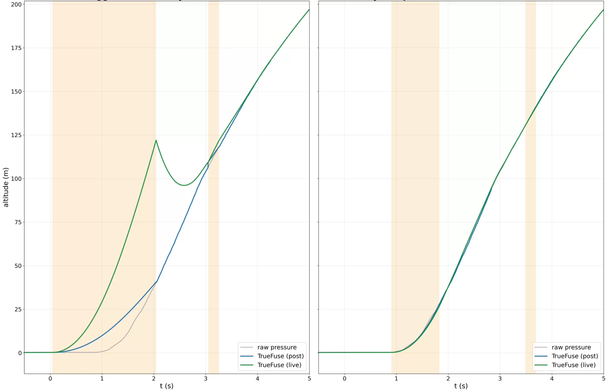
Flight 1860. Shaded bands are the repair windows. On the left, as logged. On the right, the same data with the sync corrected.
This is flight 1860, and the detected sync on it was out by 876 ms. Look at the left panel. A repair window opens almost immediately and stays open for two full seconds, and the live line climbs to about 122 m while the raw pressure and the post-processed line are both saying nearer 41 m. When the window finally closes and the filter re-anchors, the line has to come back down, so it drops to about 96 m before recovering and rejoining everything else at around 3.3 seconds. That hook is not a rocket doing anything. It is the filter correcting a fault it invented.
The right panel is the same flight with the sync corrected. The repair windows land where they should, they are much shorter, and live, post and raw pressure all sit on top of each other for the whole climb.
That is the real cost of getting sync wrong. It is not just a slightly skewed CSV. Anything that consumes both sensors inherits the error, and a filter whose whole job is to spot disagreement between them will act on a disagreement you manufactured yourself. It also told us something else, because 876 ms on one flight and 300 ms on another is not a measurement drifting a bit. It is a method that does not work reliably and should be avoided.
How we used to do it, and why it was wrong
Our firmware used to measure the offset on every flight. At launch detection it looked back through the pre-buffer and found two things: the sample where the accelerometer left the 1 g band, which is ignition, and the sample where the pressure altitude crossed the launch threshold. The difference between them became sample_sync, and the IMU columns were delayed by that many samples to meet the barometer.
It sounds reasonable. It is not, and flight 2621 shows exactly how badly it fails. On that flight the firmware decided the offset was 75 samples. At 250 Hz that is 300 milliseconds.
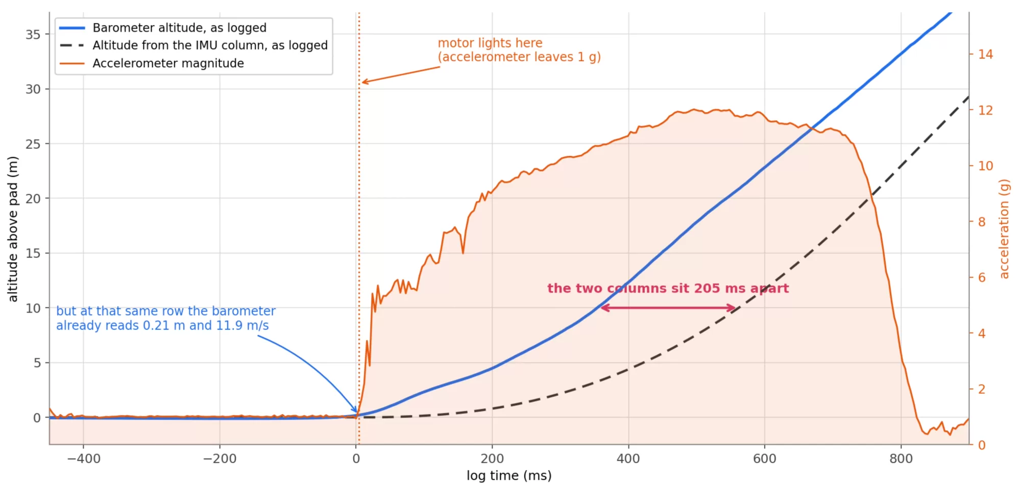
Flight 2621. At the row where the accelerometer finally leaves 1 g, the barometer column already has the rocket 0.21 m up and travelling at 11.9 m/s.
Look at where the motor lights. At that exact row the barometer says the rocket is already 0.21 m off the pad and doing 11.9 m/s. That did not happen. Nothing was moving before the motor lit. Through the whole boost the two columns sit 205 milliseconds apart, and everything downstream that mixes barometer and accelerometer data is being fed two different moments in time.
Where the 300 ms came from
Here is the bit I had wrong for a long time. The detector is not measuring sensor lag at all. It is measuring the interval between two threshold crossings, and only part of that interval is lag.
Reconstructing the real trajectory from the accelerometer, the rocket took 109 ms to physically climb from the pad to the 0.20 m launch threshold. That is not lag. That is a rocket climbing 20 centimetres, and how long it takes depends entirely on the motor. The barometer then took a further 191 ms to report it. Add them together and you get the 300 ms the firmware came up with.
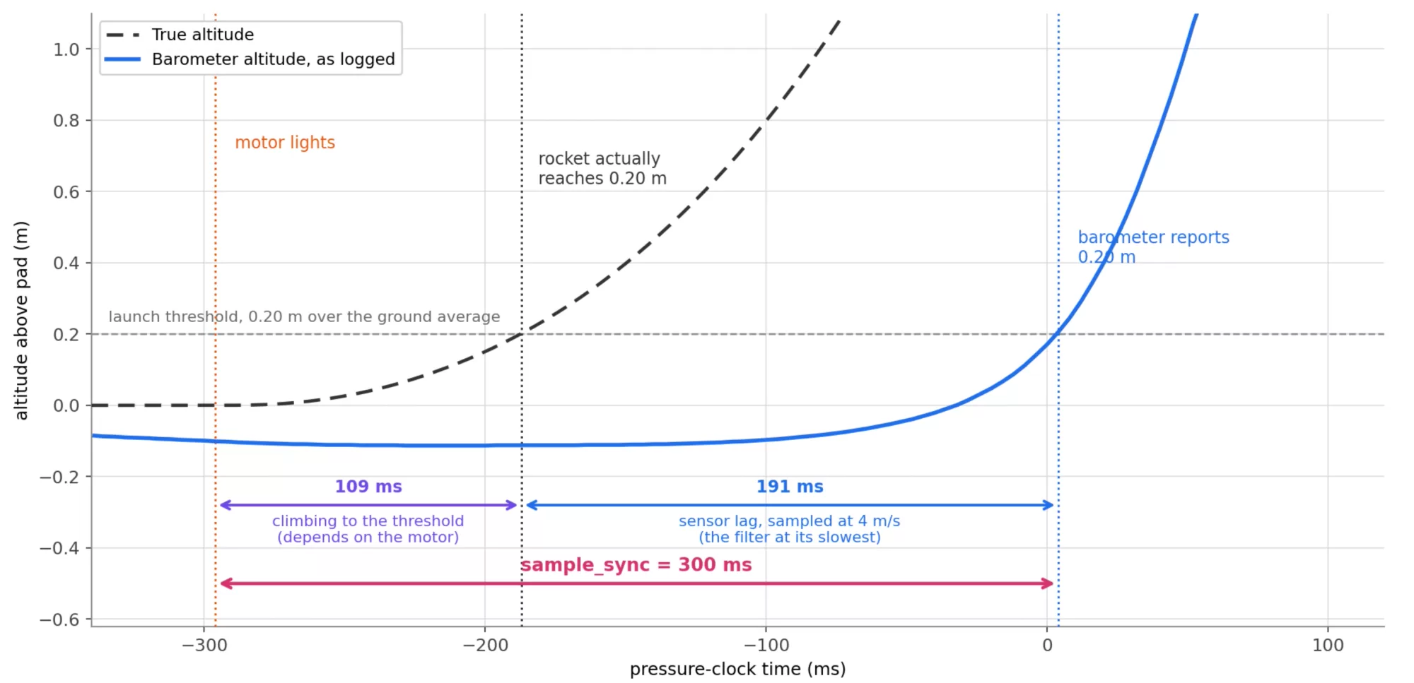
300 ms is 109 ms of rocket plus 191 ms of sensor. Neither piece is the constant we want.
Both halves are a problem. The climb time changes with every motor you fly, so a fast H will give you one answer and a lazy D will give you another, on the same board, with the same sensor, with the same actual lag. And the 191 ms is the sensor lag sampled at about 4 m/s, which turns out to be the single worst moment in the flight to measure it, for reasons I will come to. The lag for the rest of that flight was nearer 111 ms.
So the old approach was measuring a number that was partly the motor, partly the pad noise, partly the ground reference, and only partly the thing it was supposed to be measuring. It was never going to be repeatable.
The lag is not a mystery, it is arithmetic
The thing that finally clicked is that there is nothing to discover here. Every term in the delay follows from configuration the firmware already knows at boot: which sensor is fitted, the oversampling, the IIR coefficient, the filter setting and the sample rate. You do not need a flight to find it out. You can calculate it before the rocket ever leaves the ground.
tsync = tconv/2 + Todr/2 + ciir × Todr + tkal(v) − timu
Five terms, and only one of them is at all awkward.
| Term | What it is |
|---|---|
| tconv/2 conversion centring |
The ADC integrates pressure across the whole conversion window, so the number that lands in the register represents the middle of that window rather than the end of it. Half the conversion time. |
| Todr/2 polled read age |
If you poll the sensor rather than reading it on its data ready interrupt, you get whatever conversion last completed. Averaged over a lot of reads its mean age is half an ODR period. If you do use the interrupt, drop this term. |
| ciir × Todr sensor IIR |
The Bosch IIR is a single pole, y += (x - y) / (c + 1). Against a ramp it settles exactly c samples behind. The samples are the sensor's, at the sensor ODR, not your loop rate. This is normally the biggest term by a mile, and getting the wrong rate here is the classic mistake. |
| tkal(v) software filter |
Whatever your own altitude filter adds. For a SimpleKalmanFilter it has to be solved for, because the gain is not fixed. This is the only term that changes with airspeed. |
| timu IMU lag, subtracted |
Subtracted, not added. The accelerometer has a small delay of its own, roughly 1.5 of its ODR periods, and all you actually care about is the difference between the two sensors. Small, but free to include. |
The Kalman term, which is the sneaky one
SimpleKalmanFilter does not have a fixed gain, so you cannot just look its lag up. Against a steady climb the gain settles at the point where
where s is the true climb per loop, which is v divided by the loop rate. That is a quadratic in K, so it solves cleanly:
tkal = (1 − K) / K × Tloop
Two things about this term are worth knowing, and they are the reason the old detector was doomed. It is the only part of the whole budget that depends on how fast the rocket is going, and it gets slower as the rocket gets slower. On our configuration it runs about 15 ms above 50 m/s, but nearer 160 ms in the first moments off the pad.
Which is exactly where launch detection measures it. The detector samples the lag at the one instant in the entire flight when the filter is at its worst, then applies that number to the whole flight.
The fix is to pick a reference speed somewhere useful, evaluate it once, and treat it as a constant. Between 30 and 100 m/s the whole budget moves by about 5 ms, which is well under one sample at any rate we run. One number per configuration is plenty.
If your firmware scales the filter's process noise with the sample rate, as ours does, scale q the same way before you put it into the equation. Otherwise the answer is only right at one rate.
Working it through
Our newer boards run a BMP581 at OSR x16 and an ODR of 80 Hz, IIR coefficient 7, a SimpleKalmanFilter with emea 0.03 and q 0.008, a 250 Hz loop and the IMU at 416 Hz. That gives:
| conversion centring | 11.4 / 2 | 5.70 ms |
| polled read age | (1000/80) / 2 | 6.25 ms |
| sensor IIR | 7 × (1000/80) | 87.50 ms |
| Kalman at 50 m/s | solved | 15.44 ms |
| IMU lag | 1500 / 416 | −3.60 ms |
| total | 111.3 ms |
111.3 ms, which at 250 Hz is 28 samples. Not 75.
The same firmware on our older boards, which carry a BMP390 at OSR x8 and an ODR of 50 Hz, comes out at 179.0 ms. Almost all of that difference is the IIR term. Seven samples at 20 ms is 140 ms, against seven samples at 12.5 ms which is 87.5 ms. If your older boards have always seemed to lag much worse than your newer ones, that is usually why, and it is the sensor ODR doing it rather than the filter setting.
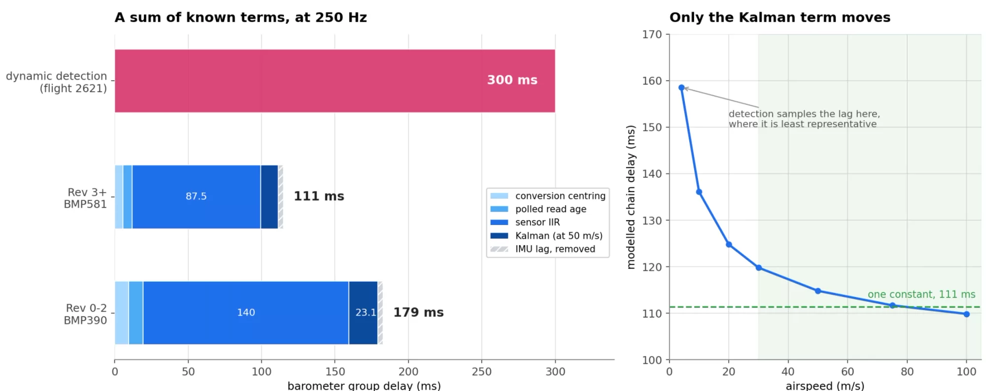
The budget for both sensors, with the detected 300 ms for comparison, and how little the total moves once the rocket is actually moving.
Values at each rate, IIR coefficient 7
Kalman columns are process noise 0.08, 0.04 and 0.02 expressed at 50 Hz. Milliseconds, with the sample count in brackets.
BMP581, OSR x16, ODR 80 Hz
| Loop rate | q 0.08 | q 0.04 | q 0.02 |
|---|---|---|---|
| 50 Hz | 90.8 (5) | 95.0 (5) | 101.5 (5) |
| 100 Hz | 93.3 (9) | 98.1 (10) | 105.0 (11) |
| 200 Hz | 102.2 (20) | 107.2 (21) | 114.4 (23) |
| 250 Hz | 106.3 (27) | 111.3 (28) | 118.4 (30) |
| 300 Hz | 106.5 (32) | 111.6 (33) | 118.7 (36) |
| 400 Hz | 106.9 (43) | 112.0 (45) | 119.1 (48) |
BMP390, OSR x8, ODR 50 Hz
| Loop rate | q 0.08 | q 0.04 | q 0.02 |
|---|---|---|---|
| 50 Hz | 155.4 (8) | 162.0 (8) | 171.8 (9) |
| 100 Hz | 158.4 (16) | 165.6 (17) | 175.8 (18) |
| 200 Hz | 167.6 (34) | 174.9 (35) | 185.2 (37) |
| 250 Hz | 171.7 (43) | 179.0 (45) | 189.3 (47) |
| 300 Hz | 172.0 (52) | 179.3 (54) | 189.6 (57) |
| 400 Hz | 172.4 (69) | 179.7 (72) | 190.0 (76) |
Dropping the IIR coefficient to 3 takes 50 ms off the BMP581 figures and 80 ms off the BMP390 ones. At coefficient 1 it is 75 ms and 120 ms.
If you are running a BMP280
Plenty of hobby altimeters still use the BMP280 or its BME280 sibling. The same equation applies, but two of the conventions are different and both bite.
The IIR coefficient means something else. The BMP280 datasheet defines the filter as (old × (coef − 1) + adc) / coef with coef of 2, 4, 8 or 16, where the BMP390 uses (old × c + adc) / (c + 1) with c of 1, 3, 7, 15. So a BMP280 "filter 16" is a 15 sample pole, not a 16 sample one. Subtract one from the setting before it goes into the equation. The datasheet's own step response column, listing 2, 5, 11 and 22 samples to reach 75 percent, is exactly what poles of 1, 3, 7 and 15 produce.
You do not choose the ODR. This is the one that matters. In normal mode the output rate falls out of the oversampling and the standby time together, ODR = 1 / (measurement time + standby), and the IIR runs at that rate. So standby time multiplies straight into the biggest term in the budget. Measurement time is 1 + 2×osrs_t + 2×osrs_p + 0.5 ms typical, which reproduces every row of the datasheet timing table.
Sensor-side terms only, at the minimum 0.5 ms standby, so add your own software filter and subtract your own IMU lag.
| Setting | ODR | Sensor lag |
|---|---|---|
| x16 / x2, filter 16 | 26.3 Hz | 608 ms |
| x16 / x2, filter 4 | 26.3 Hz | 152 ms |
| x8 / x1, filter 4 | 50.0 Hz | 80 ms |
| x8 / x1, filter off | 50.0 Hz | 20 ms |
| x4 / x1, filter off | 83.3 Hz | 12 ms |
The practical advice for a BMP280 in a rocket is minimum standby, hardware IIR low or off, and do the smoothing in software where you can account for it. At x8 with the filter off it is only about 20 ms behind, better than anything else on this page. You pay for that in noise, which is what the software filter is for.
Does it actually work
Fair question, and an equation that agrees with itself is not evidence. So I checked it two ways against the same flight.
First, I reconstructed the real trajectory by integrating the accelerometer, scaled so that it lands on the barometric apogee. It needed a factor of 0.970, which put the reconstructed apogee at 189.8 m against the barometer's 190.3 m. Then I ran that reconstruction forwards through a simulation of the entire chain: conversion window, 80 Hz sampling, IIR at coefficient 7, the zero order hold from polling, and the Kalman at loop rate. The simulated barometer sits on top of the logged one to 0.73 m rms through the boost and 1.2 m across the whole flight. The model of the chain is right.
Second, the straightforward test. Line the columns up with 300 ms, then with 111 ms, and see which one agrees with itself.
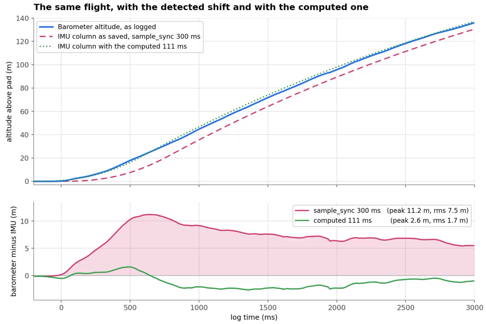
With 300 ms the columns disagree by up to 11.2 m and never fully close. With the computed 111 ms it stays inside 2.6 m for the whole flight.
Peak disagreement drops from 11.2 m to 2.6 m, and rms from 7.5 m to 1.7 m. What is left over is partly the accelerometer reconstruction's own error and partly the Kalman term genuinely wandering with airspeed, which is exactly what the model predicts it should do.
Putting it in firmware
Compute it once at boot, after sensor detection and after settings have loaded. Convert to samples at your loop rate, round, and delay the IMU columns by that many samples. Keep whatever time based ceiling you already have as a backstop, because a belt and braces cap costs nothing.
Going in as code rather than a lookup table matters more than it sounds. New sample rates and new settings then fall out on their own, instead of needing another row adding to a table that somebody forgets about.
One thing this does not fix. Lining the columns up makes the two sensors mutually consistent, but it does not pull the barometer forward onto real time, and it does not move your t = 0. On most firmware, ours included, t = 0 is placed where the pressure trace crossed a launch threshold, which is later than actual ignition by the group delay plus however long the rocket spent climbing to that threshold. On flight 2621 that is 300 ms. Different problem, different fix, and one for another article.
Two things to check before you trust a number
The conversion time for the BMP581 at OSR x16 is the one figure here I inferred rather than took from a published formula. It comes from the highest ODR the part will accept at that oversampling, about 87.6 Hz. The BMP388 and BMP390 figure is the datasheet formula and can be relied on directly. If you run a different oversampling on a 581, look it up rather than scaling my number.
And check your library, not your settings menu. Some libraries name a temperature oversampling constant something like OVERSAMPLING_SKIP when it is really x1 rather than genuinely off. At least one hard codes the IIR setting inside its begin() call, so the coefficient your menu offers never actually reaches the sensor and you sit on the default forever. Thirty seconds with the header saves a lot of confusion later.
The code
Help yourself. It has no dependencies beyond math.h.
// ---------------------------------------------------------------------------
// baro_sync.h
// Neil Bowen - AltimeterCloud.com
//
// Barometer group delay, computed from configuration instead of detected at
// launch.
//
//   t_sync = t_conv/2 + T_odr/2 + c_iir * T_odr + t_kal(v) - t_imu
//
// Call it once, after sensor detection and settings load. The result is the
// number of milliseconds by which a logged pressure altitude sits behind the
// truth, so it is also the amount by which the IMU columns should be delayed
// to line the two streams up.
//
// Assumes the firmware polls the sensor (rather than reading it on its data
// ready interrupt) and passes the altitude through a SimpleKalmanFilter at the
// loop rate. If your pipeline differs, the first three terms still hold and
// the Kalman term is whatever your own filter contributes.
// ---------------------------------------------------------------------------
#ifndef BARO_SYNC_H
#define BARO_SYNC_H

#include <math.h>

struct BaroSyncCfg {
  float t_conv_ms;    // sensor conversion time at the configured oversampling
  float odr_hz;       // sensor output data rate in flight (NOT the loop rate)
  float iir_coeff;    // Bosch IIR coefficient: 0, 1, 3, 7, 15, 31 (0 = bypass)
  float e_mea;        // Kalman measurement uncertainty
  float q_base;       // Kalman process noise, expressed at 50 Hz
  float loop_hz;      // firmware sample rate
  float imu_odr_hz;   // IMU output data rate in flight
  float v_ref_ms;     // reference airspeed for the Kalman term, m/s
};

// Steady-state lag of a SimpleKalmanFilter tracking a constant-rate ramp.
// The gain settles where K^2 * e_mea = q * s * (1 - K), with s the true climb
// per loop, and the estimate then trails the measurement by (1 - K)/K loops.
static inline float kalmanLagMs(float e_mea, float q, float v_ms, float loop_hz) {
  if (q <= 0.0f || e_mea <= 0.0f || v_ms <= 0.0f || loop_hz <= 0.0f) return 0.0f;
  const float T_loop_ms = 1000.0f / loop_hz;
  const float s  = v_ms / loop_hz;
  const float qs = q * s;
  const float K  = (-qs + sqrtf(qs * qs + 4.0f * e_mea * qs)) / (2.0f * e_mea);
  if (K <= 0.0f || K >= 1.0f) return 0.0f;
  return (1.0f - K) / K * T_loop_ms;
}

static inline float baroSyncMs(const BaroSyncCfg &c) {
  const float T_odr_ms = (c.odr_hz > 0.0f) ? 1000.0f / c.odr_hz : 0.0f;
  const float q        = c.q_base * (50.0f / c.loop_hz);  // scaled with dt

  const float t_conv = c.t_conv_ms * 0.5f;         // value is the mid-conversion instant
  const float t_poll = T_odr_ms * 0.5f;            // mean age of a polled sample
  const float t_iir  = c.iir_coeff * T_odr_ms;     // c samples at the SENSOR rate
  const float t_kal  = kalmanLagMs(c.e_mea, q, c.v_ref_ms, c.loop_hz);
  const float t_imu  = (c.imu_odr_hz > 0.0f) ? 1500.0f / c.imu_odr_hz : 0.0f;

  return t_conv + t_poll + t_iir + t_kal - t_imu;
}

static inline int baroSyncSamples(const BaroSyncCfg &c) {
  return (int)lroundf(baroSyncMs(c) * c.loop_hz / 1000.0f);
}

// Conversion time in ms, Bosch BMP388 and BMP390 datasheet formula.
// Pass the oversampling factors themselves, so x8 pressure and x1 temperature
// is bmp390ConvMs(8, 1).
static inline float bmp390ConvMs(int osr_p, int osr_t) {
  return (234.0f + (392.0f + osr_p * 2020.0f) + (163.0f + osr_t * 2020.0f)) / 1000.0f;
}

// BMP581 at pressure OSR x16 with temperature at x1, from the highest ODR the
// part accepts at that oversampling. Inferred, not from a datasheet formula.
#define BMP581_CONV_MS_OSR16  11.4f

// --- BMP280 and BME280 ------------------------------------------------------
// Typical measurement time in ms, datasheet Table 13. Reproduces all five
// tabulated rows. Pass oversampling factors, or 0 for a skipped channel.
static inline float bmp280MeasMs(int osr_p, int osr_t) {
  float t = 1.0f;
  if (osr_t > 0) t += 2.0f * osr_t;
  if (osr_p > 0) t += 2.0f * osr_p + 0.5f;
  return t;   // worst case is roughly 15% longer, see the datasheet max column
}

// Normal-mode ODR: one measurement plus one standby period. You do not set
// this directly on a BMP280, which is why a long standby is so expensive.
static inline float bmp280OdrHz(int osr_p, int osr_t, float standby_ms) {
  return 1000.0f / (bmp280MeasMs(osr_p, osr_t) + standby_ms);
}

// A BMP280 filter setting of 2, 4, 8 or 16 is a pole of 1, 3, 7 or 15.
// Do not pass the raw setting into the equation.
static inline float bmp280IirCoeff(int filter_setting) {
  return (filter_setting >= 2) ? (float)(filter_setting - 1) : 0.0f;
}

#endif  // BARO_SYNC_H
And calling it:
int   sample_sync    = 0;    // samples the IMU columns get delayed by
float sample_sync_ms = 0.0f;

void computeSync() {
  BaroSyncCfg c;

  if (hasBMP581) {
    c.t_conv_ms = BMP581_CONV_MS_OSR16;   // OSR x16
    c.odr_hz    = 80.0f;
    c.e_mea     = 0.03f;
  } else {
    c.t_conv_ms = bmp390ConvMs(8, 1);     // OSR x8 pressure, x1 temperature
    c.odr_hz    = 50.0f;
    c.e_mea     = 0.0625f;
  }

  c.iir_coeff  = (float)iirfilter;        // 0, 1, 3, 7, 15, 31 as set
  c.q_base     = kalmanProcessNoise();    // 0 if the filter is bypassed
  c.loop_hz    = (float)sample_speed;
  c.imu_odr_hz = imuOdrForRate(sample_speed);
  c.v_ref_ms   = 50.0f;                   // reference airspeed

  sample_sync_ms = baroSyncMs(c);
  sample_sync    = baroSyncSamples(c);
}
The short version
Barometer lag is real, it is large, and on our hardware it runs from about 90 ms to about 190 ms depending on which sensor and what settings. It is not, however, mysterious. It is the sum of five terms you can write down from configuration alone, and four of them are completely fixed.
It's perhaps best if you're planning to rely on IMU's more than pressure to move the barometers timeline or vice versa depending on your needs. It also lets you fine tune when a pressure based event actually occured if more exact timing is wanted.
Trying to measure it at launch instead sounds sensible, and I ran it that way for a long while, but it cannot work. What you actually measure is the gap between two threshold crossings, which is part sensor lag, part motor performance and part pad noise, sampled at the exact moment your filter is at its slowest. On flight 2621 that produced 300 ms where the real answer was 111 ms, and the log had the rocket doing 11.9 m/s before its motor had lit. On flight 1860 it produced 876 ms, and TrueFuse spent two seconds correcting a pressure fault that only existed because the columns were skewed.