Distance
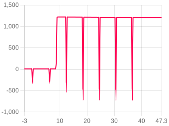
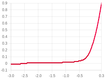
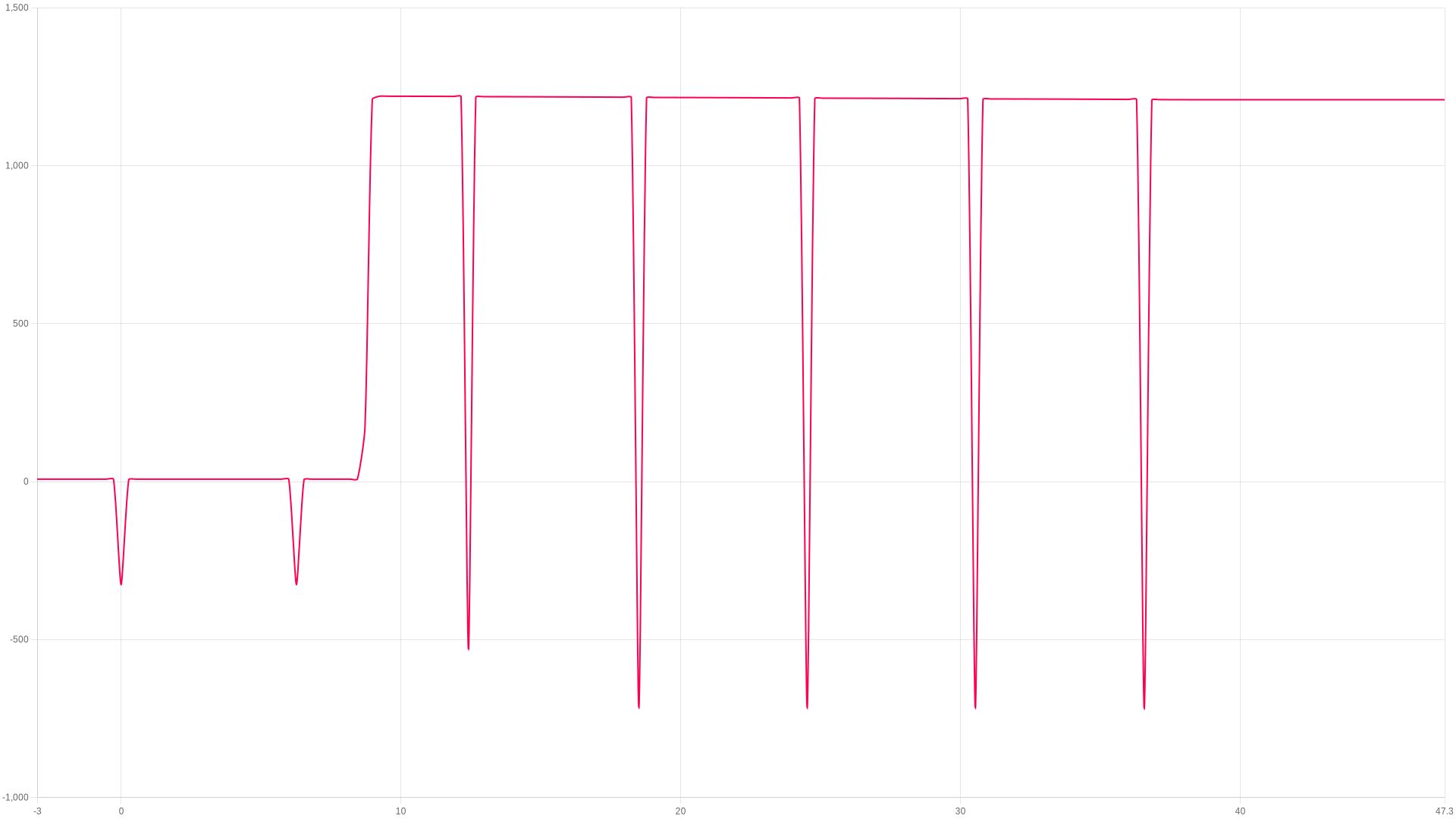
You can choose which units to use for distance from Meters(m), Feet(ft), Miles(mi) & Kilometers(km)
Velocity
You can pick which units to use for Velocity/speed such as Meters per second (m/s), Feet per second (ft/s), Miles per hour (mph) and Kilometers per hour (kph)
Acceleration
You can choose acceleration units to display from either Meters per second squared (m/s^2) or Gravity (G)
Flight 1112

Flight 1112

Mercury V1 Rev 2 · firmware 2.1
Apogee
1219.95m
9.24 s after launch
Max ascent
364.79m/s
peak ascent
Max during burn
17.95G
during the burn
Landing
34.63s
touchdown 57.89 m/s
ZOOM TO
s
s
Show events
Adjust temp & pressure ?
Image
Zooming
Drag to zoom, pinch on mobile
Compare flight ?
Flight summary

The flight, moment by moment

Liftoff
0 s
Launch pad tilt64.63°
Thrust calc pad tilt
Burnout (first)
0 s
Altitude-326.28 m
Velocity0.000 m/s
Apogee
9.24 s
Altitude1219.95 Meters
Max tilt to burnout67.59°
Landing
34.63 s
Altitude1210.36 m
Max descent-111.76 m/s

Stability0.1%Poor

Launch straightness (20%)0
20% · Launch tilt 0°
Coning · full (25%)0
25% · Coning 0/0°/s
Coning · boost (25%)0
25% · Spin 0°/s
Thrust straightness (30%)0
30% · Thrust 0%
Battery & temperature 18% → 18% · Temperature start -67.76 → -121.17 °C · Launch after startup 2m 6s

About the stability score

Worked out from the flight log between liftoff and 80% of apogee. It is independent of the angle the altimeter was mounted at, so it measures the flight rather than the fitting.

Launch straightness (20%)20%How close to vertical it left the rod.
Coning · full (25%)25%How much the nose swung off the rocket's own axis across the whole ascent.
Coning · boost (25%)25%The same swing during the burn, when it matters most.
Thrust straightness (30%)30%How cleanly the motor pushed along the body.

Spin about the rocket's own axis is not counted against it — a fast, straight spin is stable. The figures beside the score are the raw measurements behind these four.

Altitude
Apogee1219.95 Meters
Time to apogee9.24 s
Burnout altitude-326.28 m
Max velocity altitude1210.05 m
Ejection altitude-326.28 m
Landing altitude1210.36 m
Recording altitude3606.31 m
Velocity
Max ascent364.79 m/s
Max descent-111.76 m/s
At burnout0.000 m/s
Descent velocity-2.887 m/s
Ejection velocity-0.69 m/s
Landing velocity57.893 m/s
Acceleration
Max during burn17.95 G
Max ascent36.67 G
Max descent45.16 G
Average ascent18.78 G
Average burnN/A
Times
Burnout (first)0 s
Apogee9.24 s
Possible ejection0 s
Landing34.63 s
Output #1 ON0 s
Output #1 OFF0 s
Angles
Launch pad tilt64.63°
Thrust calc pad tilt
Max tilt to burnout67.59°
Launch roll64.62°
Launch pitch1.35°
Max spin (burn)0 dps
Avg spin (burn)0 dps
Recovery
Single deploy
No dual deploy detected on this flight.
General
Upload date22-Jan at 04:21
Data samples825
Total recording time106.700 s
Average samples/s7.7
Number of lockouts5
Launch after startup2m 6s
Reference axisY
Battery & temperature
Battery start18%
Battery end18%
Temperature start-67.76°C
Temperature end-121.17°C
MT1 launch temp0°C
⚠ Low power — charge before next flight
Output rules
No rules configured
User notes
No notes added
Add this device to your account to edit
Youtube video
No video added
Add this device to your account to edit
Flight images 0
No images added
Flight motors
No motors have been added to this flight
Add this device to your account to edit
Linked rocket
No rocket linked to this flight
Output rules
Rules allow the Mercury to take actions based on flight conditions. Each rule has up to 4 conditions (A-D) that must be met before the action triggers.
No rules configured
Motor match (BETA)
No motor matches, try refreshing the page.

Linked flights

Connect flights that belong together: a second altimeter flown in the same rocket, or the same rocket flown again. Linked flights appear on each other’s pages.

No linked flights yet.

Launch site, date & time

Click anywhere on the map to mark your launch site. Switch between map and satellite view using the buttons below.

Imagery © Esri, Maxar, Earthstar Geographics

Click the map to place a marker · Drag to adjust

No launch site has been set for this flight.

Flight data animation

FLIGHT 1112

1219.95 Meters

ALTITUDE
0.00m
VELOCITY
0.00m/s
ACCEL
0.00G
TILT
0.00°
PITCH
0.00°
ROLL
0.00°
YAW
0.00°
TIME
0.00s
AWAITING LAUNCH
ALT
altimetercloud.com
LAUNCH T+0.00s LANDING

BURNOUT

Motor burn complete

Note: Flight profile animation requires your altimeter to be mounted in a fixed orientation that you choose in your settings. For best results please calibrate your sensors as well.
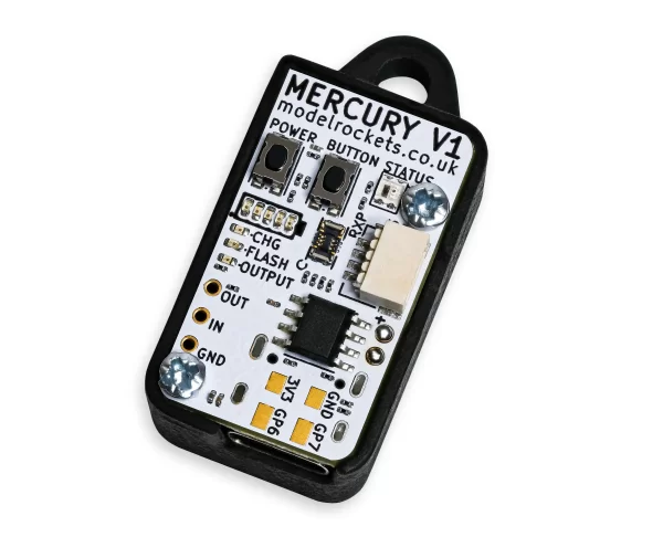
Mercury V1
Revision 2
Mercury V1
This flight was flown on a Mercury V1.
The hardware
Hardware versionRev 2
Software version2.1
Last online27-Jan at 01:02
Pressure sensorBosch BMP 390
Accelerometer32G 3-axis
Gyroscope2000 dgps 3-axis
MagnetometerN/A

Settings, as they were for this flight

General flight settings
Forecast pressure
i
Set this to your local forecast pressure at sea level. This will offer you slightly improved accuracty for your flight, although it's not 100% essential every little helps!

Xcweather.co.uk is a decent place to grab pressures from for your location and time.
999 mbar
Launch detect
i
This is the altitude above the launch pad altitude where the altimeter will trigger itself into recording / flight mode.

The altimeter keeps a constant average of the pressure while waiting for launch, it uses a simple algorithm and the pre-flight buffers to do this. The most recent 120 samples (~4 seconds) are ignored so your pre-trigger altitude won't effect the ground baseline.

For almost all uses we suggest keeping this on the 25 Meter (~82 feet) default settings. If you want to test your altimeter by throwing it in the air, or are planning a very low flight you may want to lower the setting.
1 meters
Sample ratio
i
The altimeter runs at 50Hz however you can record every sample or every X samples in order to extend the log time. For example if you set the ratio to 1 it will save 1:1 samples, or if you set it to 3 it will save 1 in 3 samples.
1:1 (50Hz)
Max samples
i
This is the maximum samples the altimeter will log per flight. When it reaches this amount it will stop and save the recording.
12000
Recording stop
i
This setting is how the altimeter decides to stop recording. You can choose either 450 (~9s) or 900 (~18s) samples stable or it will record until the max samples limit unless you press the BUTTON in Manual stop mode.

The samples stable method waits for the devices altitude not to change for the set number of samples. This is defined by not changing by more than +/- 1.0 meters for 98% of the samples, it's a reliable method to stop the recording after landing within 8-10 seconds (300 sample) or 16-20 seconds (600 sample).
Auto: 450 samples stable (~9s)
Oversampling
i
Oversampling is a internal setting of the BMP 390 pressure sensor. It is how many samples are taken for each reading. By taking multiple samples for each pressure reading the altimeter reduces noise and increases the resolution of the output.

The sensor can run at 50 samples per second in 4X mode, so we suggest leaving it in this mode as it will offer the highest accuracy.
8x Oversampling
IIR filter
i
The IIR filter is another internal sensor for the BMP390 pressure sensor. It is a Infinite impulse response filter used to enhance pressure measurement accuracy by reducing noise. It's primarily for smoothing out rapid pressure changes.

We suggest not setting this too high as it will cause delay to changes in altitude if set very high.
COEFF 7
Pressure filter
i
This filter is a software Kalman filter that runs on the altimeters processor.

The Kalman filter uses a prediction step based on a system model and then a correction step using new measurements to refine its estimate, it creates accurate most certain results from data with noise in it.
Kalman 2 (default)
Lockout time
i
The Lockout time is how long the altimeter should stop making decisions and taking actions if it detects unusual high speed altitude changes that are unexpected.
These false readings can be caused by ejection charges (if the altimeter is in the same compartment as the motor ejection gases) or even when you transition to Mach speeds and can give false readings of altitude changes.

When these events are detected the system enters Lockout for the specified time while it stabalises. This effects things like triggering the output, or calculating other data.
750ms
Lockout change
i
This is how we detect a lockout. If the pressure changes by this much in a single sample downwards (pressure increase, lower altitude) then it's likely to be a false reading. Multiply the setting by 32 to get the speed in meters per second that it will trigger at.
1.5 meters
Sync sensors
i
The filters on the pressure sensor can cause it to lag very slightly behind the Accelerometer and Gyroscope data. The Sync sensors option detects how far out of sync these sensors are. It then corrects the Acceleration and Gyroscope readings to match the pressure sensor.
ENABLED
Orientation
i
This is the orientation you intend to install the Altimeter in your rocket. It's needed to ensure completly accurate angles and orientation charts and reports. Check out the Manual for more information on this.
Upwards (text up)
IMU filter
i
The IMU filter, or fusion filter takes the data from each axis of the Gyroscope and Accelerometer to calculate the Pitch, Roll, Yaw and tilt angle from vertical. These filters can build up some discrepency over time so it's important to calibrate your sensors to minimise this.
Madgwick 6-Axis
Launch ALP
i
This is prevention against accidental launch detection.

With this disabled the launch is based only on pressure and something that creates a low pressure can trigger the flight by accident. For example pulling your nose cone off can even trigger it.

With this enabled the rocket also needs to have seen 8 samples (0.25 seconds) of acceleration above this setting in the last 3 seconds as well as the pressure drop to trigger. There is a backup trigger of 1.05 seconds of altitude being above the launch detect setting too.

There are very few situations where this option would cause issues, so we suggest leaving it on.
1.4G
Launch lock
i
When enabled, the altimeter locks out recording for a set period after power on to prevent false triggering during setup.
DISABLED
Static temperature
i
A fixed temperature value used for altitude calculation when the external temperature sensor is disabled or not connected.
8.00 °C
Temp sensor
i
If an external MT1 temperature sensor is connected, this controls whether it is used for logging only or also for altitude calculations.
DISABLED
Output settings
Output 1 enabled
i
Disable or enable the output from being able to turn on or off.
DISABLED
Output 1 trigger
i
After apogee (altitude)
This method triggers when the altitude drops below the set altitude after apogee is detected.
After apogee (time)
This method triggers the defined seconds after apogee is detected.
After launch (altitude)
This method is activated if/once the altimeter exceeds the set altitude after launch.
After launch (time)
This option triggers the defined seconds after launch is detected.
After burnout (time)
This method triggers the defined seconds after burnout is detected.
After apogee (altitude)
Output 1 time on
i
This is how long the output should trigger ON state when the rules are met.
2000ms
Output 1 altitude
i
This is the altitude to trigger at if using a trigger method that works on altitude.

For example if you set this to 75m and After apogee (altitude) for the trigger then the output will turn on at 75m on descent above the launch altitude.
0 meters
Output 1 time
i
This is the time variable for output triggers that work on time.

For example if you set this to 3 seconds and After apogee (time) as the trigger then the output will turn on 3 seconds after apogee.
0 seconds
Altitude lock
i
Altitude lock is a safety feature that prevents the output from triggering if the altitude is below this level when the rules are met.
50.00 m
Tilt angle lock
i
This is another safety feature. It can be used to disable the output if the rocket has gone too far from vertical.

For example if you set the tilt angle lock to 40 degrees then the output will not fire if the rocket is more than 40 degrees from vertical. To disable set this to 0.
0.00 °
Sensor calibration
Calibration offsets used during this flight.
Gyroscope⚠ Gyroscope has not been calibrated
X0.000°
Y0.000°
Z0.000°
Accelerometer
X-29.770 mG
Y-27.110 mG
Z55.880 mG
Device settings
Device TAG
i
A custom name or tag assigned to this device for easy identification.
Merc8139
Language
i
The language setting configured on the device.
en
Shutdown mode
i
Controls what happens after recording. Standard shuts down normally, Delayed keeps WiFi on for 30 seconds after landing, Stay on keeps the device powered on.
Delayed 30s
LED brightness
i
The brightness level of the LED indicators on the Mercury. Lower values save battery.
20%
WiFi TX power
i
WiFi transmit power level. Higher gives better range but uses more battery.
5 dBm (default)
Sleep mode
i
Controls whether the device enters low-power sleep when idle.
Normal (sleep when idle)
Battery monitor
i
Monitors battery voltage during the flight.
DISABLED
Cloud group
i
The cloud group / category this flight is assigned to.
GP6 / GP7 ports
Configuration for the GP6 and GP7 general purpose output ports. These ports can drive pyro channels, servos, or other devices.
Channel 6 mode
ON = HIGH
Ch6 min pulse (µs)
1000
Ch6 max pulse (µs)
2000
Ch6 frequency
50 Hz
Ch6 angle ON
170.00°
Ch6 angle OFF
10.00°
Ch6 on time
2.00s
Channel 7 mode
ON = HIGH
Ch7 min pulse (µs)
1000
Ch7 max pulse (µs)
2000
Ch7 frequency
50 Hz
Ch7 angle ON
170.00°
Ch7 angle OFF
10.00°
Ch7 on time
2.00s
I2C PCA9685 Servo Board
Configuration for the external I2C PCA9685 servo expansion board. This board provides up to 6 additional servo channels.
No I2C servo board was connected for this flight.
Prediction and air brakes
The Mercury can predict apogee while coasting after burnout. These settings control the prediction calculation and optional air brake system.
Dry mass
i
The total mass of the rocket after motor burnout (dry mass). This is used for the ballistic prediction of apogee altitude. Enter the mass without the motor propellant, or the mass at burnout.
0.0200 kg
Drag Cd
i
The aerodynamic drag coefficient (Cd) of the rocket. This is used with the rocket area to calculate aerodynamic drag during coast. A typical model rocket has a Cd of 0.4 to 0.8. You can find this value from OpenRocket or RockSim simulations.
1.000
Reference area
i
The cross-sectional reference area of the rocket in square meters. This is typically the area of a circle with the body tube diameter. For example a 38mm tube has an area of approximately 0.00113 m².
0.00400 m²
Gas constant
i
The specific gas constant for dry air, used in the atmospheric model for altitude and density calculations. The standard value is 287.05 J/(kg·K). You shouldn't need to change this unless you know what you're doing.
287.05 J/(kg·K)
The following settings configure the air brake system.
Air brake enabled
i
Enables or disables the active air braking system. When enabled, the Mercury will deploy air brakes via the configured servo channel to try and reach the target altitude. Firmware 2.1+ required.
OFF (default)
Servo channel
i
Which servo output channel the air brake mechanism is connected to. GP6 and GP7 are the two onboard servo headers, I2C channels are for an external servo expander board.
GP6
Deploy speed
i
The speed at which the air brakes deploy. The Mercury gradually increases the servo angle until the predicted apogee matches the target rather than going full on/off. This setting controls how quickly it ramps up to full braking.
Medium (default)
Target altitude
i
The target apogee altitude in meters. The air brake system will try to slow the rocket so it reaches this altitude.
300.00 m
Over shoot %
i
The percentage over the target altitude to aim for until within 15% of the target. This helps prevent undershooting if the prediction is slightly off early in the coast. For example, with a 1000m target and 5% early adjustment, the Mercury will aim for 1050m until it passes 850m.
5.00%
Activation altitude
i
The air brake system activates after burnout, but won't engage until the rocket has reached this percentage of the target altitude. This prevents the brakes from deploying too early when predictions may be less accurate.
20% (default)

Files

Where the altimeter signs its log, the file carries that signature and a tick beside it. A tick means the data is unchanged since the device wrote it, which is what a record claim needs.
CSV
1112.csv
The log as columns of text. Opens in a spreadsheet, and in every simulator that reads flight data.
72 KB
Adjusted CSV2904 recalculated in your browser
The log recomputed for your own sea-level pressure and temperature. Columns: time, altitude as recorded and adjusted, raw altitude as recorded and adjusted, pressure.

This file is built here from the signed log, so it carries no signature of its own. Anyone verifying a claim should be sent to the flight page and build their own from the original.

Flight
Comments
Sign in to leave a comment.