The easiest way to configure your altimeter is via the Altimeter Cloud. If you have not already, you can use the Altimeter Cloud WiFi guide to get your device connected.
Finding the device settings page
![]()
Click on the My Devices tab at the top of the Altimeter Cloud website. You will see a list of devices on your account. Click the Settings button on the device you want to configure.
When you click save, the settings are transmitted to your altimeter. This typically takes 1 to 4 seconds as long as your altimeter is turned on and connected to WiFi.
The default settings are a great starting point for most flights, so don't be overwhelmed by the number of options available. These offer advanced tuning and additional features should you need them. For most flights the Mercury only needs to be turned on and it's ready to go.
Forecast pressure

The forecast pressure is the weather forecast pressure at sea level for your launch site location. The standard default is 1013.25 mBar which is the atmospheric average. Your altimeter will work well on this default, however for the highest accuracy you should enter the forecast pressure for the day and time you are flying. It makes more of a difference if you're launching from high altitude sites or on days with extremely low or high pressure.
A good website in the UK to look up these pressures is xcweather.co.uk.
Launch detect

The launch detect setting tells the altimeter how high it must reach (pressure altitude) before it triggers launch detection and starts recording. The default setting of 25 meters is perfect for almost all occasions. The lower settings are for very low altitude flights that might not reach 10 to 20 meters, or for testing your device by throwing it in the air.
Note: Pressure sensors are light sensitive, so if you mount your altimeter directly in your electronics bay or don't use the default Mercury case, you should try to ensure light cannot get into the sensor. It will dramatically increase the noise in your altitude readings.
Note: Pulling your nose cone or body tube apart can cause a vacuum pressure that might trigger the altimeter's launch detection. We have a system to protect against this that is on by default, so please also read about Launch ALP further down the page.
Your altimeter does not use a fixed pressure from when the device was turned on as a reference for the launch pad altitude. Instead it constantly updates an average from around 5 to 10 seconds of data at 50 times per second. This means if you turn it on lower or higher than your launch pad, or it sits for a while on your pad, changes in atmospheric pressure will not affect the accuracy of your flight data.
Sensor speed

The Mercury runs it's sensors at 100Hz by default. Which we suggest sticking too by default. You can drop this down to 50Hz if you like but it has very few benefits bar a few percent more battery life.
Sample ratio

The Mercury runs at a 50Hz or 100Hz cycle rate taking readings from the sensors and making calculations. You can choose how often to log these samples to the flight log.
By default the Mercury will log every cycle, giving you maximum detail. You can use this setting to log every 1, 2, 3 or 4 samples instead. This allows you to record for longer within the 12,000 sample limit per flight.
Hybrid modes start at full 1:1 resolution and then switch to a reduced ratio ten seconds after apogee. This gives you maximum detail during the powered and coasting phases while extending the total recording time significantly. For example, hybrid mode can extend recording from around 4 minutes to over 8 minutes.
They also jump back to 1:1 sample ratio when the altitude drops below 20m on descent to capture landing at full speed too.
It is also possible to use the Rules system to change the logging rate after specific events or time. For example you could configure a rule to drop the sample ratio after apogee.
Max samples

The Max samples setting is the number of lines in your flight log or sample count when the recording will automatically stop. The maximum is 12000 samples per flight, but if you wish to run for a fixed time you can disable the automatic stop and set the maximum samples as you require.
Recording stop

The recording stop determines when to end a flight recording. The default setting of auto (450 samples stable) will be perfect for the vast majority of flights.
The auto stop analyses the last 450 or 900 samples and if 98% of these are within a small distance of the recent average, the Mercury is deemed to have stopped moving for a significant time and the recording will be stopped. There is also a manual stop mode, where you need to press the BUTTON (not the POWER BUTTON) to stop the recording.
Once a recording finishes the status light will turn PINK while the flight logs are saved into the flash memory. After this is complete the device will turn itself off, so don't panic if you get to your rocket and your device is off — it has recorded and you didn't forget to turn it on.
Oversampling

This is the setting for the BMP390 pressure sensor that tells it how many internal samples to take for each sample it outputs. The BMP390 supports up to around 205Hz of samples. You should leave this on the default 8X setting. The only advantage to dropping it is a few percent extra battery life.
Oversampling allows the pressure sensor to increase its precision. Each increment from no oversampling increases the output accuracy by 1 bit. For example, 1x oversampling offers 16-bit pressure resolution with around 20cm altitude resolution, whereas 4x oversampling offers 18-bit and around 5cm resolution.
Later revisions from revision 3 use a BMP581 pressure sensor that operates even faster and has a default oversampling rate of 16X. There really are few reasons to decrease this.
IIR filter

The IIR filter is the second internal filter on the BMP390 or BMP581 pressure sensor. IIR stands for Infinite Impulse Response, and in practice it is an efficient filter that smooths multiple samples. This helps remove sudden spikes and noise such as wind blowing into the sensor.
For most uses you will want this set to 1, 3 or 7, but do feel free to experiment. If set too high it can cause problems with precision at peaks and during rapid altitude changes. High settings will cause a slight delay in the output reaching the actual altitude, but can offer great results for slow moving items like weather balloons.
Pressure filter (Kalman)

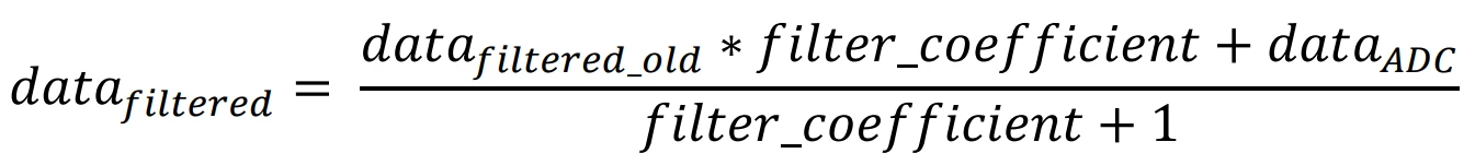
The pressure filter is a Kalman filter that runs on the processor rather than on the sensor. You can choose from 4 settings: OFF or three levels of filtering. This is an advanced filter that estimates the real pressure based on current and historical samples.
The middle setting works perfectly for most flights. You can tell the filter to do more or less filtering with the other options. Kalman filters are extremely good at removing noise from sensor data, leaving a greatly improved and more realistic altitude path.
Lockout time

The lockout filter detects events that cause the pressure sensor to read the wrong altitude. This might be an ejection charge going off, which increases pressure inside the rocket and makes the sensor think there has been a sudden drop in altitude. Another common cause is rockets entering supersonic speeds, which also causes pressure disruption.
This setting controls how long the device should lock itself out from making decisions on outputs and other calculations when it detects one of these events. The default of 500ms works well for most situations.
Lockout change

The lockout sensing works by detecting if the altitude has dropped so rapidly that it exceeds this amount between a single sample. While these values seem small, remember it's working at 50 samples per second (the value is doubled automatically in 16 samples per second mode).
A 1.5m drop between samples is the equivalent of dropping at 48 meters per second or around 107 mph — which under normal operation your rocket should not be achieving in a downward direction.
Sync sensors

Different sensors have different filters and this can cause a small amount of delay in the data of one sensor versus another. The result is that different sensors will be slightly out of sync with each other.
This setting enables the re-sync algorithm. It looks back when launch is detected for the likely launch event in each sensor. It then shifts each sensor's data in the buffer relative to the pressure sensor to resynchronise them. Recommended to leave enabled.
IMU filter

The IMU filter fuses together the 6-axis data from the gyroscope and accelerometer to calculate angles such as pitch, roll, yaw and the tilt angle from vertical. The Madgwick filter uses slightly more processing power but is more accurate than the Mahony filter.
The Mercury doesn't have a magnetometer for 9-axis fusion, so small errors will build up over time. From our testing these are very small and the filter offers great data over the duration of a standard rocket flight.
To get the best results you should calibrate your sensors and mount your altimeter in one of the supported orientations.
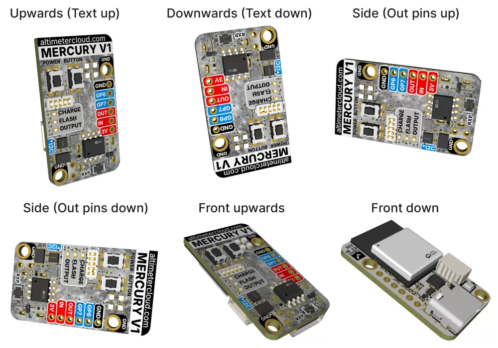
Orientation

The orientation setting tells the altimeter which way up you plan to install it. While it can work this out itself, this setting ensures the IMU filter receives the correct axis data in the correct order for accurate angle calculations. The default is upright with the USB port pointing downwards.
Launch ALP (Accidental Launch Prevention)

This setting helps prevent accidental launch detection. Without ALP, the altimeter relies solely on the pressure sensor and the altitude it indicates. This means strong gusts of wind, or even pulling your nose cone off, could cause a pressure change large enough to trigger launch detection.
With ALP enabled, the altimeter uses both the pressure sensor and the accelerometer to verify launch. In order to trigger, the altimeter needs to see 8 samples in the last 3 seconds above the set G acceleration level as well as the altitude exceeding the launch detect threshold.
There is also a backup trigger: once the altimeter has been above the launch threshold for 1.05 seconds it will trigger launch detection regardless. This ensures genuinely slow launches are still detected.
Launch lock

This setting prevents the altimeter from detecting a launch under any circumstances until the specified time has passed since you turned the Mercury on. For example, if you set this to 180 seconds (3 minutes) then your altimeter will wait until this time has elapsed before looking for launch detection. For most uses it's best to leave this set to 0.
Static temperature

When calculating altitude from pressure, the equation uses both the Forecast pressure setting and this static temperature setting. The defaults are 1013.25 mBar and 15.0°C respectively.
If you change these to actual values on the day of your flight you will get the most accurate altitude calculations.
Temp sensor

The onboard temperature sensor will be affected by the board's own heat and the fact the inside of your rocket is unlikely to reflect the external temperature. You can connect one of our tiny MT1 temperature sensors to the I2C expansion port on your Mercury for a much more accurate reading (0.1°C accuracy).
Once connected you can choose to either log the MT1 temperature to your flight log, or both log it and use it as the static temperature at launch for altitude calculations.
If you plan to use it as your static temperature, take care to install the sensor so it can sample the temperature outside your rocket on the shady side while on the launch pad, and ideally insulate it from any internal heat.
Output #1

The Mercury has an onboard high current output that can be used to fire pyrotechnic deployment charges, activate a buzzer, or drive other loads. The output needs to be supplied with an external battery with a voltage range of 4V to 22V and is current limited to 10–12 Amps maximum.
The connection points on the Mercury's PCB are a 2mm pitch, so you could potentially solder on header pins or a PCB terminal block as well as direct wires.
Note: If you solder onto the board you will be unable to return the device within the 14 day return period, although this does not affect your warranty for faults.
Output enabled
Use this option to enable or disable the output. If disabled, the output will not activate under any circumstances. This is a safety feature — always leave it disabled unless you have a specific need for it and have tested your configuration.
Output trigger
This setting controls what event triggers the output. The available options are:
- After Apogee (altitude) — fires when the altitude drops below a specified value after apogee. For example, if you set 200 meters, the output will fire when the rocket descends to 200 meters below apogee.
- After Apogee (time) — fires a specified number of seconds after apogee is detected.
- After Launch (altitude) — fires when the rocket reaches a specified altitude during ascent.
- After Launch (time) — fires a specified number of seconds after launch is detected.
- After Burnout (time) — fires a specified number of seconds after motor burnout is detected.
- Landing — fires when landing is detected.
Time on
This setting controls how long the output stays active once triggered, in seconds. For deployment charges this is typically kept short (0.5 to 2 seconds). If you need the output to stay on for the entire flight (for example driving a buzzer), set this to a high value.
Altitude (meters)
This value is used if you pick a trigger that works on altitude. If you select "After Apogee (altitude)" it will trigger after apogee when the altitude drops below the number you choose. If you select "After Launch (altitude)" then the output will trigger once the altitude reaches the value you set during ascent.
Time (seconds)
This is the time delay for your chosen trigger option. If you select "After Apogee (time)" the output will fire this many seconds after apogee. If you select "After Launch (time)" it will trigger this many seconds after launch is detected. The same applies for the burnout option.
Altitude lock
This safety setting prevents the output from being activated if the rocket is within this altitude of the launch pad. This protects against the output firing while the rocket is still on or near the ground, for example during an aborted launch or very short flight.
Tilt angle lock
This safety setting prevents the output from firing if the tilt angle is outside of this amount from vertical. This is particularly important for deployment charges — if your rocket has tipped over significantly, you may not want it to fire a parachute deployment charge pointing sideways or downwards.
Device TAG

The Device TAG is found under the General settings tab. This lets you configure a name or tag for your device. All flights uploaded will be assigned the tag you set, so you can change it as needed. You can then search on the Altimeter Cloud for your tag to find specific flights. Useful if you have multiple Mercury altimeters or want to tag flights for specific rockets.
Group

The Group option lets you select standard groups to add your flight into them if applicable and you want to keep track amongst other flights.
LED brightness

The onboard LEDs are bright and if you don't need them at full brightness you can save power and waste heat by dimming them. Our default setting is 20% and we think this is plenty for most uses.
Battery bar

From hardware revision 2 there is a 5-LED battery bar on the board. This is permanently on during USB mode to show the state of charge.
During flight mode, to minimise power usage, there are 3 options:
1 LED blink (default) — only blinks the current state's single LED every few seconds.
5 LED blink — blinks the battery state as a conventional bar with all LEDs up to the current state illuminated every few seconds.
Button only — only shows the battery state in flight mode when you press the button, for a short period.
Smart power mode (eMode)
Power saving mode while waiting on the launch pad. There are two options:
eMode 1 — runs sensors at 50Hz and snaps to full speed on motion detect. A good balance of responsiveness and power saving.
eMode 2 — the CPU wakes at 25Hz and batch-reads IMU data from the sensor FIFO. Sensors stay at 52Hz in low-power mode. This halves the CPU duty cycle for lower pad power consumption. The battery bar is disabled and the status LED blinks every 8 seconds instead of being constantly on. Snaps to full speed on motion detect.
Requires firmware 2.3 or later.
eNOW
eNOW enables your Mercury to transmit short-range pings after a flight is saved, broadcasting information such as your apogee altitude and battery level. The range is approximately 80 to 300 meters depending on conditions and landing orientation. Requires firmware 2.2 or later.
eNOW: Enable — turns the eNOW transmitter on or off.
eNOW: Interval — controls how frequently the pings are transmitted.
eNOW: Startup — (coming soon) this feature will broadcast your most recent flight summary when turned on, allowing other devices to receive flight data.
WiFi power off

This tells the altimeter not to stay on indefinitely when in WiFi / Settings mode. After the set amount of time your device will turn off. It's easy to turn back on and quick to reconnect to the Altimeter Cloud should you need to update any settings again later.
UART

This setting enables a Serial UART that streams sensor data and information at 50Hz on the GP6 and GP7 solder pads. When enabled you will be unable to use these pads for servos or other outputs.
The UART runs at 921600 baud, 8 bits with 1 stop bit to maximise battery life. GP6 is the TX pin (connect to your RX) and GP7 is the RX pin (connect to your TX). You will see around a 5% drop in battery life when using UART mode.
Warning: The UART runs in 3.3V mode. Please do not transmit to the device as it serves no function, and especially do not send a 5V signal as this could damage your Mercury.
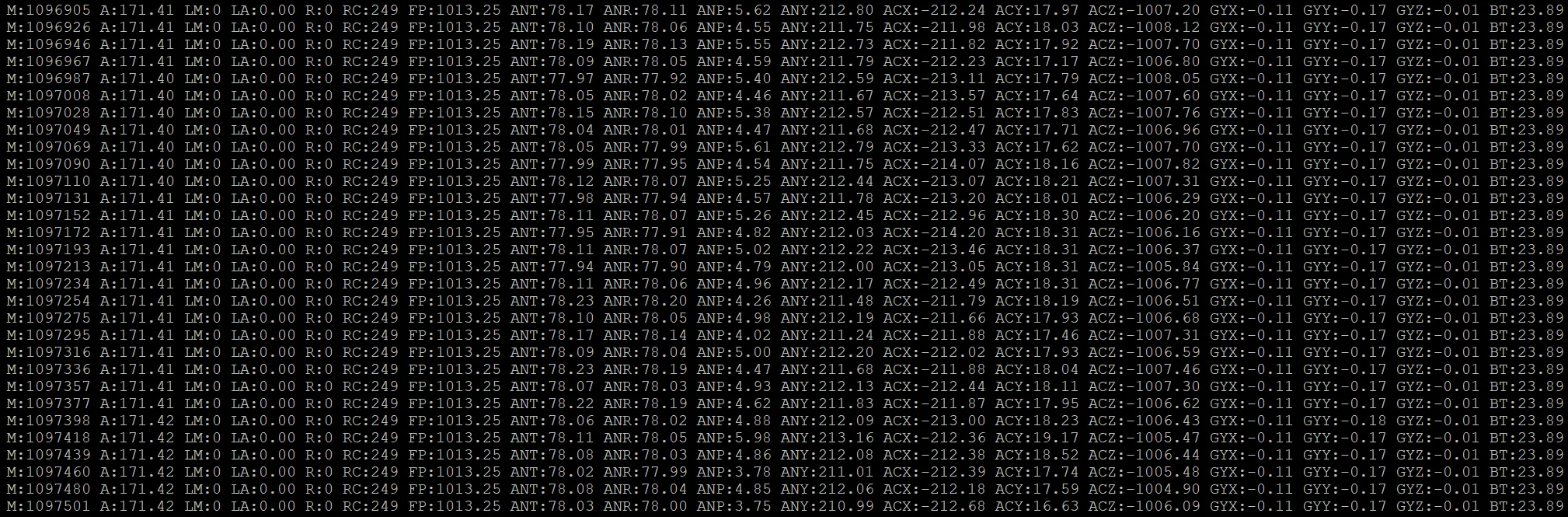
The streaming output variables are:
M: Milliseconds since the Mercury was powered on.
A: Current altitude in meters.
LM: Milliseconds when the rocket left the pad (if launch detected).
LA: Altitude of the pad at launch. Subtract from current altitude for live flight height.
R: 1 if the device is recording.
RC: Number of samples in the flight log (shows 249 when not recording — this is the pre-flight rolling buffer).
FP: Forecast pressure being used.
ANT: Tilt angle from vertical (degrees).
ANR: Roll angle (degrees).
ANP: Pitch angle (degrees).
ANY: Yaw angle (degrees).
ACX/ACY/ACZ: Acceleration for each axis (-32000 to +32000 mG).
GYX/GYY/GYZ: Gyroscope for each axis (-2000 to +2000 dps).
BT: Board temperature from the pressure sensor.
MT1: MT1 temperature sensor reading (if connected).
Device language

This sets the native language for the device interface, used for the device's web server and access point connection. Several languages are offered and more may be added in future firmware.
Sensor calibration

For the most accurate data we recommend calibrating your sensors. Tick the calibration checkbox and save — the calibration will run the next time the device enters flight mode.
There is a dedicated page covering the calibration process: View calibration guide
Servo support (GP6 & GP7)

The Mercury has two general purpose solder pads (GP6 and GP7) that can each be configured as either a standard HIGH/LOW output or a servo signal output. When configured as a servo you can set the min/max pulse widths, frequency, ON/OFF angles, and hold time. These outputs are controlled via the action rules system. Requires firmware 2.0 or later.
There is a dedicated page covering servo configuration: View servo configuration guide
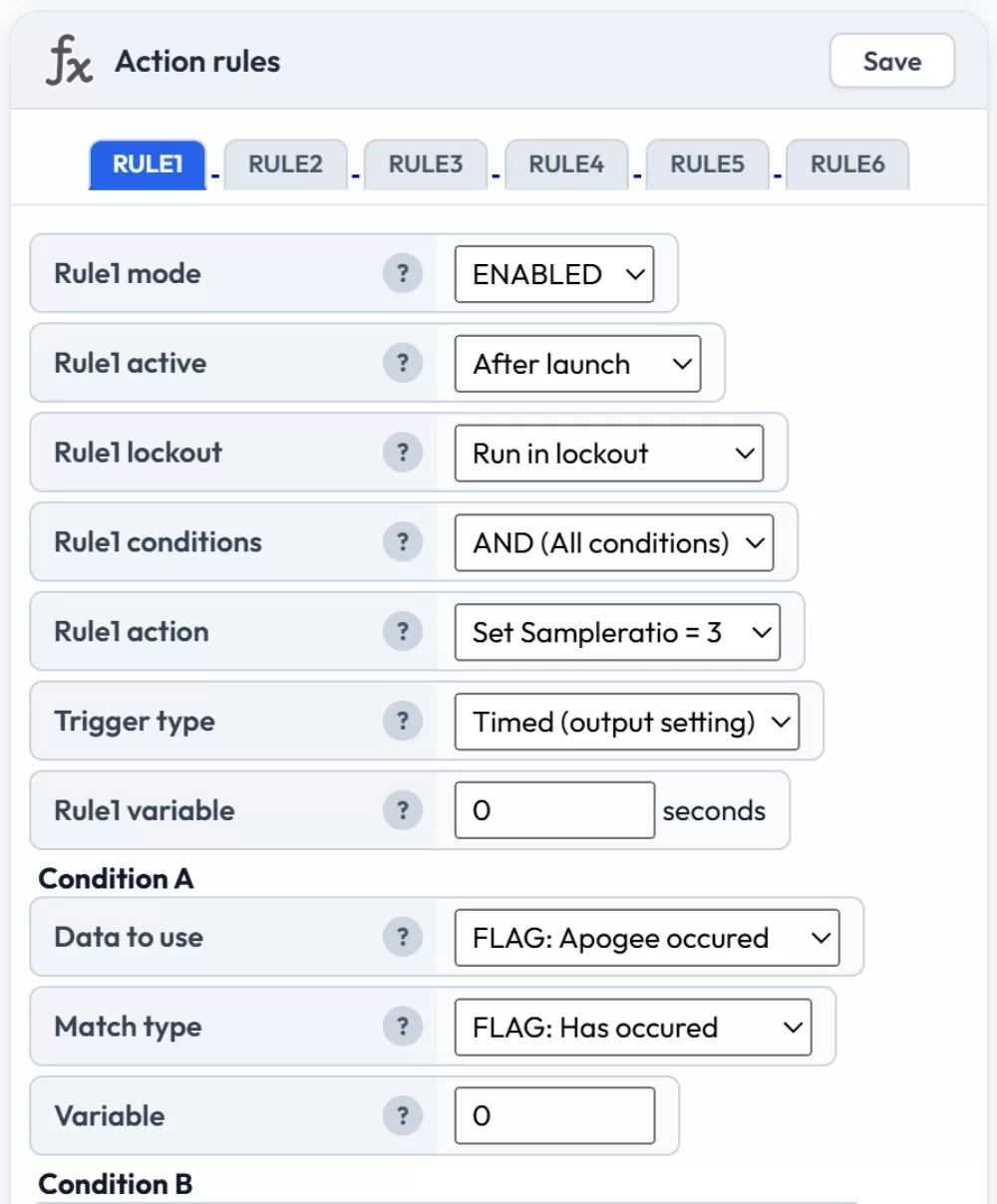
Action rules

The rules system is the most powerful feature of the Mercury. You can create up to 6 independent rules, each with up to 4 conditions that must be met before the action triggers. Rules can control outputs, servos, sample ratios, and more.
There is a dedicated page covering the action rules system with examples: View action rules guide
Prediction & air brakes

The Mercury can predict apogee altitude during the coast phase after motor burnout. This information appears on your flight charts and can also be used to drive an active air brake system. Requires firmware 2.1 or later.
There is a dedicated page covering prediction and air brakes: View prediction & air brakes guide
ROC2 high current output board
The ROC2 is an expansion board that provides two additional high current outputs. Enable the board in settings, then configure each output channel with the same trigger options available for Output #1. The ROC2 outputs can also be controlled via the action rules system using the ROC2 OUT1 and ROC2 OUT2 actions.
If the ROC2 board is enabled in settings but not physically detected when entering flight mode, the status LED will flash red for 5 seconds as a warning.
I2C PCA9685 servo expansion board
You can connect a PCA9685-based I2C servo expansion board to your Mercury, providing up to 6 additional servo channels. These servos are controlled through the action rules system, allowing complex multi-servo setups for air brakes, fin control, payload deployment, or other mechanisms. Requires firmware 2.0 or later.
Settings include the board enable toggle, oscillator frequency (default 25 MHz — adjust only if your board uses a different crystal), and individual servo configuration for each of the 6 channels including min/max pulse width and frequency.
WiFi settings
You can configure up to 4 WiFi networks. The device will connect to whichever saved network has the strongest signal. This is useful for having your home WiFi, a mobile hotspot for the field, and perhaps your club's launch site WiFi all saved.
WiFi settings don't take effect until the next time WiFi starts. You can trigger this by unplugging and re-inserting the USB-C cable or turning the device off and back on.
Warning: If you enter incorrect WiFi credentials, your device may lose its connection to the Altimeter Cloud. You will need to connect to it via its access point WiFi to correct the settings.
WiFi TX power
The transmit power of the WiFi radio. Higher values give better range but use more battery.