The Mercury allows you to configure six custom rules each with up to 4 conditions. These can control outputs, servos, air brakes, and change configuration variables as needed.
There is a simple output control setting option as well. You can use either or both systems as they work independently from each other.
The rule configuration box
When triggering outputs or servos, these need to be configured first via the servo settings or the Output #1 settings on the settings page. The rules can then trigger these outputs as they are configured. It's worth noting that the main output on time is set in the Output #1 settings even if you are not using the simple output trigger (you can leave it disabled but just set the ON time option).
When configuring a rule you need to change the mode from DISABLED to ENABLED and configure all the settings as you need. You can set up to 4 conditions for each rule and decide if all conditions must be met, or if any single condition is enough to trigger the rule.
Rule settings
Mode
Enables or disables the rule. To use a rule, change this to enabled.
Active
Controls when the rule can run. Choose whether the rule is always active (even while waiting on the pad before launch) or only active after launch is detected. For most deployment rules you will want "after launch only".
Lockout
If the altimeter detects a rapid pressure increase (such as from an ejection charge or supersonic transition), it enters lockout mode. During lockout the altitude is deemed unreliable and the altimeter postpones making decisions that it might get wrong. This can be configured in the flight settings.
Use this setting to decide if your rule should run during lockout (useful for functions not affected by pressure, such as time-based triggers) or if it should only run outside of lockouts.
Conditions (AND / OR / Grouped)
Controls how multiple conditions are evaluated:
AND (All conditions) — the rule will only trigger if every condition (A, B, C, D) is met simultaneously during the same cycle.
OR (Any condition) — the rule will trigger if any single condition is met.
(A+B) OR (C+D) — conditions A and B must both be true, OR conditions C and D must both be true. This gives you two independent condition pairs in a single rule. For example, you could trigger an output if (apogee has occurred AND altitude is below 100m) OR (time after launch exceeds 60 seconds AND velocity is below 5 m/s) — covering both a normal dual deploy and a failsafe timeout in one rule. Requires firmware 2.3 or later.
Action
This tells the rule what to do when its conditions are met. The available actions are:
- OUTPUT #1 — fires the onboard high current output
- GP6 — activates the GP6 solder pad output or servo
- GP7 — activates the GP7 solder pad output or servo
- BLOCK (perm) — permanently blocks all other rules from running for the rest of the flight
- BLOCK (v secs) — blocks all other rules for the number of seconds specified in the variable field
- End recording — stops the flight recording immediately
- Set Sample ratio = 1, 2, 3, 5, 10 — changes the logging rate mid-flight to extend recording time
- I2C Servo #1 through #6 — triggers one of the 6 channels on the PCA9685 expansion servo board
- Airbrake OFF — disables the air brake system
- Airbrake ON — enables the air brake system
- ROC2 OUT1 — fires channel 1 on the ROC2 high current output expansion board
- ROC2 OUT2 — fires channel 2 on the ROC2 high current output expansion board
Trigger type
Controls how the action behaves when triggered. This is a newer addition that gives you much more flexibility:
- Timed (output setting) — fires for the duration configured in the output or servo settings box. This is the classic behaviour.
- Timed (V1 seconds) — fires for the number of seconds specified in the rule's variable field below. This lets each rule have its own independent on-time without changing the output settings.
- Latch ON — turns the output on and keeps it on until a separate rule with Latch OFF fires. Useful for things that need to stay active for an unpredictable duration.
- Latch OFF — turns the output off immediately. Use this in combination with a Latch ON rule to create on/off pairs controlled by different conditions.
Variable
If your rule requires a variable, enter it here. For "BLOCK (v secs)" this is the number of seconds to block. For "Timed (V1 seconds)" this is the on-time in seconds. Outputs and servos that use their own configured on-time don't need this field.
Conditions
Each rule has up to 4 conditions. You need to specify at least 1 condition for a rule to work. Each condition has 3 options to set.
Data to use
This specifies what flight data the condition checks against. The available options are:
Sensor and flight data:
- Altitude above pad (m) — current altitude relative to the launch pad
- Acc magnitude (G) — total acceleration magnitude across all axes
- Acc X / Y / Z (G) — acceleration on individual axes
- Highest Gyro axis (dps) — the highest rotation rate across all gyroscope axes
- Gyro X / Y / Z (dps) — rotation rate on individual axes
- Tilt angle (degrees) — angle from vertical
- Roll / Pitch / Yaw angle (degrees) — individual orientation angles
- Velocity (m/s) — current speed of ascent or descent
- Battery (%) — current battery charge level
- Board temperature (°C) — temperature from the pressure sensor
- MT1 temperature (°C) — temperature from the external MT1 sensor (if connected)
Time-based:
- Time after launch (s) — seconds since launch was detected
- Time after apogee (s) — seconds since apogee
- Time after landing (s) — seconds since landing was detected
- Time after burnout (s) — seconds since motor burnout
Prediction and air brakes:
- Predicted apogee (m) — the current estimated apogee altitude during coast phase
- Air brake on percent (%) — how far the air brakes are currently deployed (0–100%)
Multi-stage (firmware 2.3+):
- Time after burnout 2 / 3 / 4 (s) — seconds since 2nd, 3rd, or 4th stage burnout
- Time after ignition 2 / 3 / 4 (s) — seconds since 2nd, 3rd, or 4th stage ignition
- Stage count — the number of stages detected so far
Event flags:
- FLAG: Launch occurred
- FLAG: Apogee occurred
- FLAG: Burnout occurred
- FLAG: Landing occurred
- FLAG: Burnout 2 / 3 / 4 occurred (multi-stage)
- FLAG: Ignition 2 / 3 / 4 occurred (multi-stage)
Match type
This tells the rule how to compare the chosen data against your variable value:
- (>) Greater than
- (>=) Greater or equal
- (=) Equal
- (!=) Not equal
- (<) Less than
- (<=) Less or equal
- FLAG: Has occurred — use with FLAG data options
- FLAG: Has not occurred — use with FLAG data options
Condition variable
The threshold value to compare against. For example, if you are matching when altitude drops below 80 meters, enter 80 here. Not needed for FLAG conditions.
Example: Trigger the output after apogee and under 100 meters
This example could be used for a dual deploy where your motor has ejected the first small parachute and you want to use the output to trigger a secondary parachute when the rocket falls below 100 meters.
Set the first condition to "FLAG: Apogee occurred" with match type "FLAG: Has occurred". Set the second condition to "Altitude above pad (m)" less than 100.
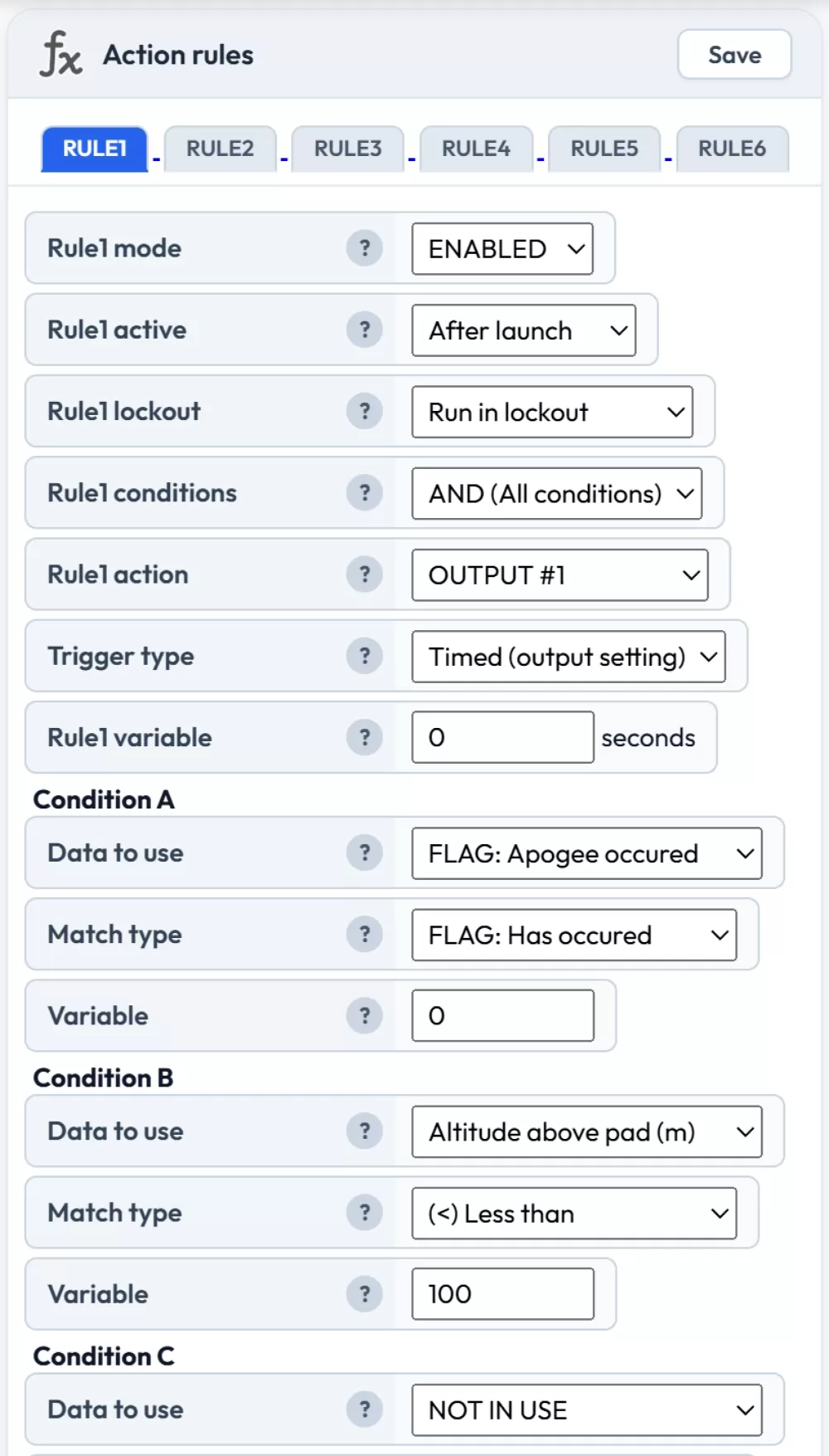
Dual deploy at 100 meters after apogee
Example: Air starting the second stage with tilt protection
This example uses two rules to ignite the second stage motor using the OUTPUT, 1 second after burnout, as long as the rocket is within 35 degrees of vertical. The second rule triggers a failsafe recovery system using the GP6 solder pad regardless of whether the second stage was fired.
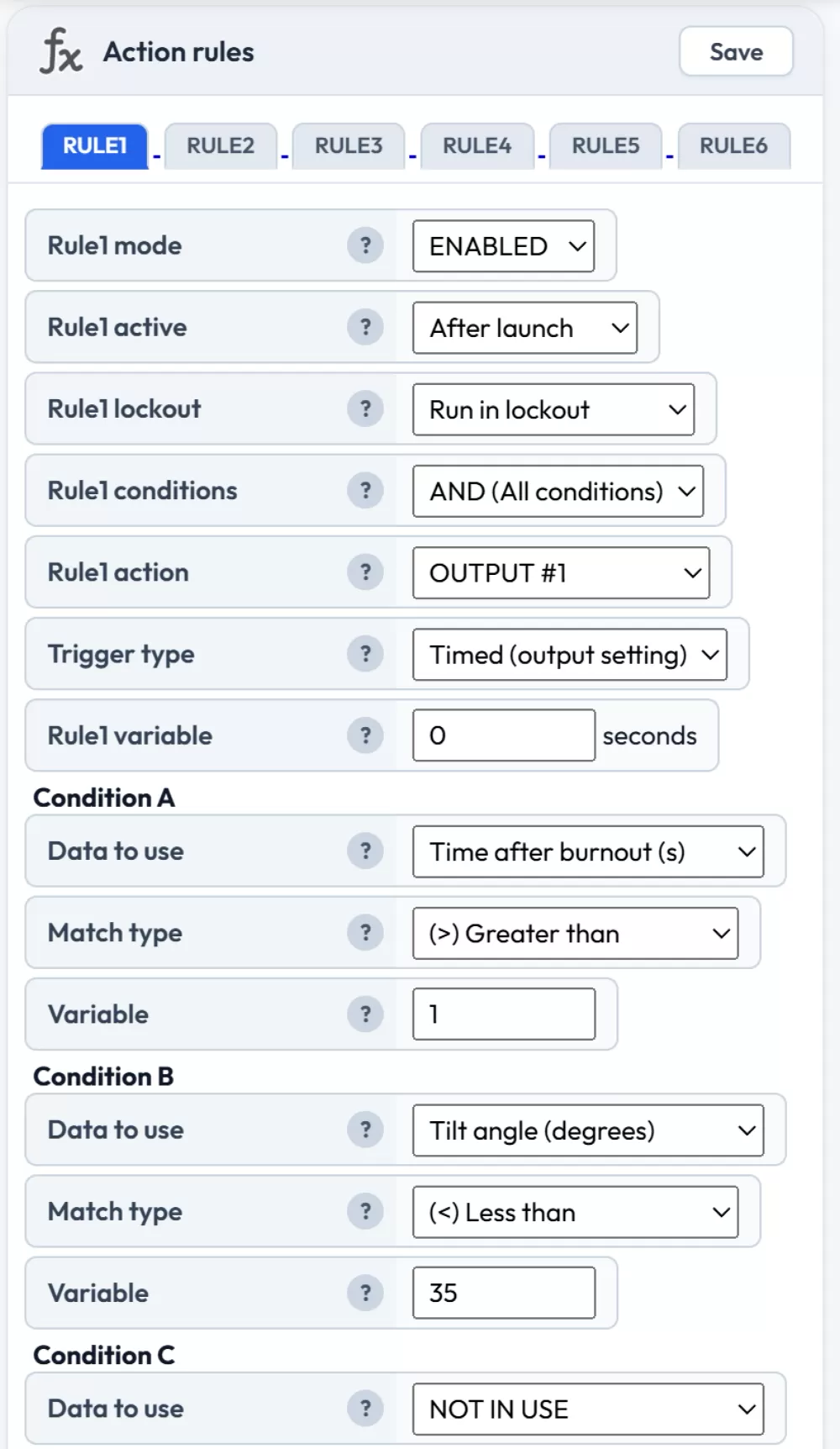
Rule 1: protected air start — fires output 1 second after burnout if tilt is under 35°
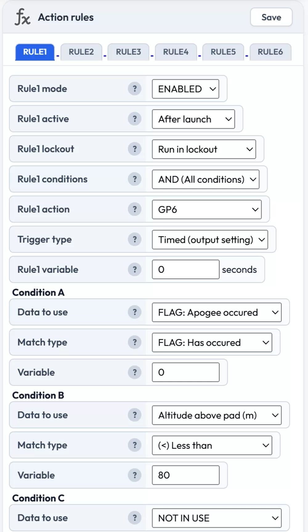
Rule 2: failsafe recovery at 80 meters via GP6
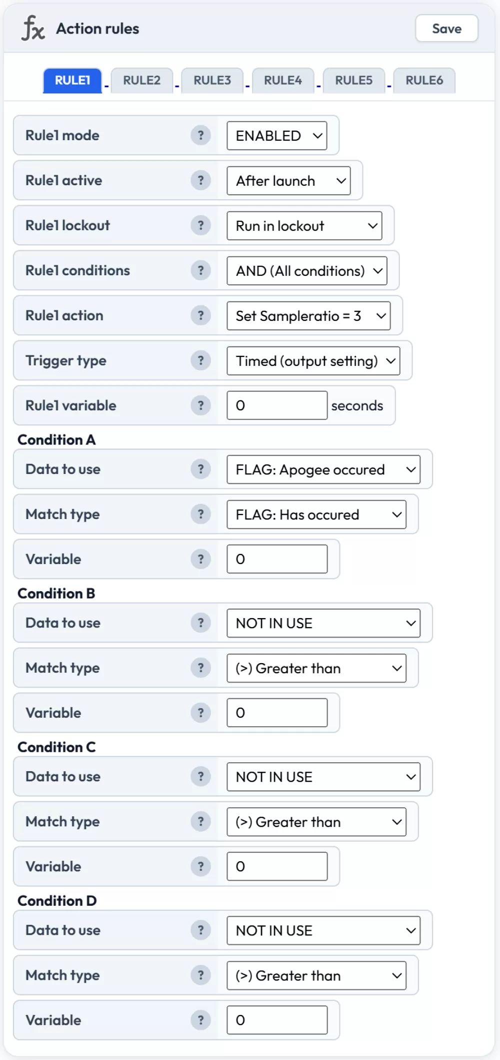
Example: Increasing sample ratio 20 seconds after apogee
This example drops the logging rate after the active flight phase to extend total recording time. The sample ratio is set to 2 (logging every other sample) when 20 seconds since apogee has passed.
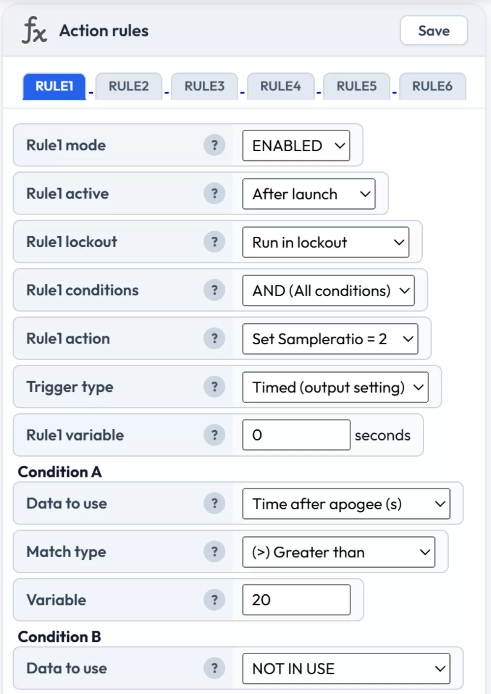
A sample ratio of 2 means we log every other sample to the flight log
Example: Block rules until 10 seconds after launch
This example prevents all other rules from running until 10 seconds after launch is detected. Useful as a safety measure to avoid premature deployment triggers during the boost phase.
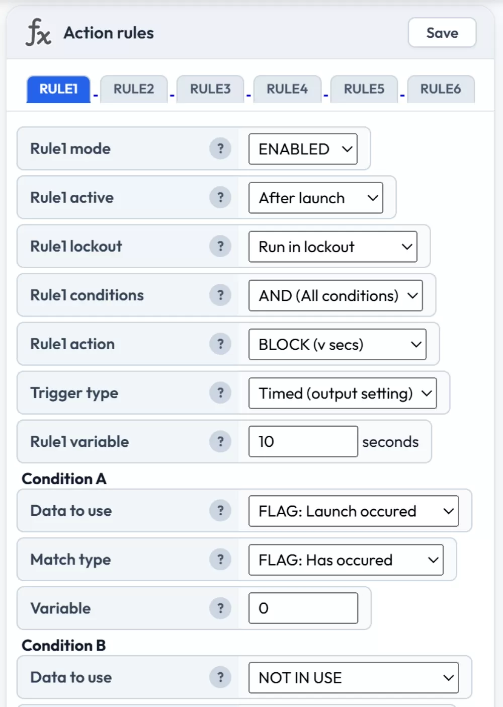
Uses BLOCK (v secs) with the rule variable set to 10
Example: Use an I2C servo to deploy a recovery system
This example triggers a servo to deploy a recovery system. It waits until at least 4 seconds after launch was detected and until the velocity has dropped below 20 meters per second.
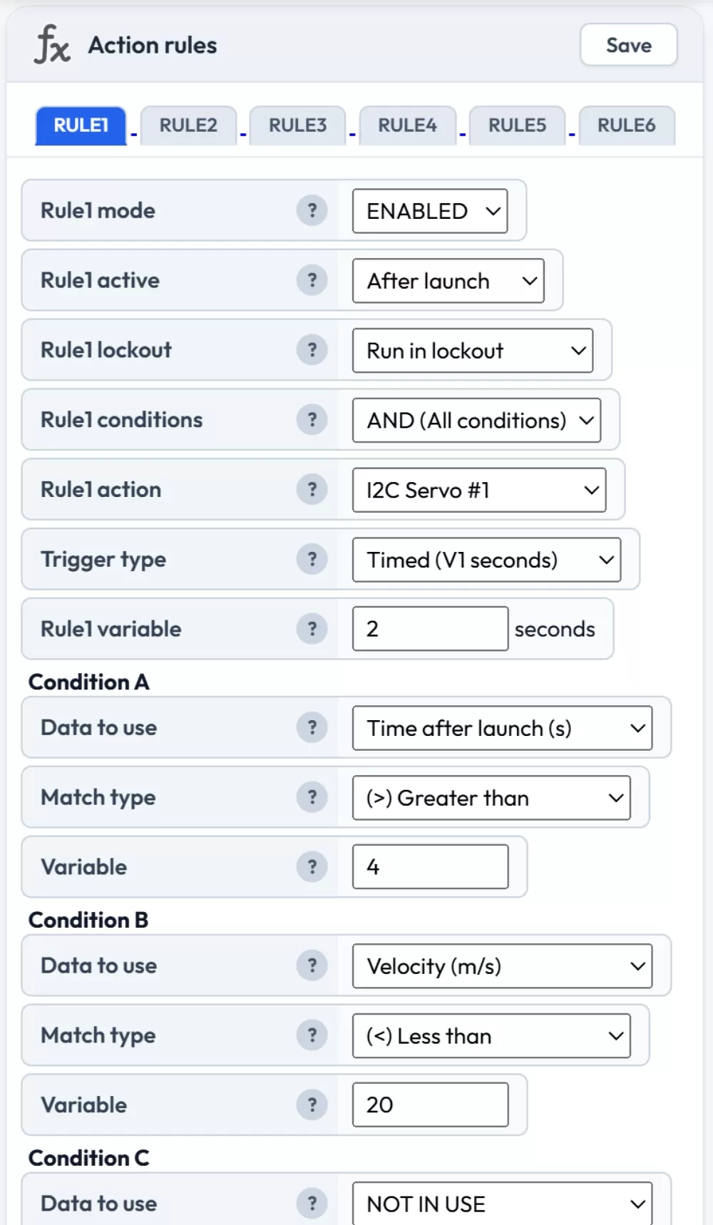
Configure the servos in the I2C Servo expansion settings
Example: Latch ON / Latch OFF for continuous output
The latch trigger type is useful when you need an output to stay on for an unpredictable duration. For example, you might want to activate a buzzer after landing and keep it on until the battery drops below a threshold.
Rule 1: Set the action to OUTPUT #1, trigger type to "Latch ON", with a condition of "FLAG: Landing occurred" — "FLAG: Has occurred".
Rule 2: Set the action to OUTPUT #1, trigger type to "Latch OFF", with a condition of "Battery (%)" less than 10.
The output will turn on when landing is detected and stay on until the battery drops below 10%.
Example: Multi-stage air start with stage detection
For multi-stage rockets, you can use the stage-specific conditions to control each stage independently. For example, to ignite a second stage motor 0.5 seconds after first stage burnout with tilt protection:
Condition A: "FLAG: Burnout occurred" — "FLAG: Has occurred"
Condition B: "Time after burnout (s)" greater than 0.5
Condition C: "Tilt angle (degrees)" less than 30
You can then use "Time after ignition 2" and "FLAG: Burnout 2 occurred" in subsequent rules to manage recovery deployment relative to the second stage's flight profile.
Example: Dual deploy with failsafe using (A+B) OR (C+D)
The grouped condition mode lets you combine a primary trigger and a failsafe backup into a single rule. For example, to deploy a main parachute either at the normal altitude or after a timeout:
Set the conditions mode to (A+B) OR (C+D), then:
Condition A: "FLAG: Apogee occurred" — "FLAG: Has occurred"
Condition B: "Altitude above pad (m)" less than 150
Condition C: "Time after launch (s)" greater than 60
Condition D: "Velocity (m/s)" less than 5
This fires the output if (apogee has occurred AND altitude is below 150m) OR (more than 60 seconds have passed since launch AND the rocket is barely moving). The second pair acts as a failsafe in case apogee detection fails. Requires firmware 2.3 or later.