It is possible to connect servos to the Mercury altimeter and use them to perform all sorts of functions with your model rocket, such as deploying air brakes, triggering recovery systems, controlling fin angles, or releasing payloads.
The configuration process is split into two steps. First, you configure your servos including the angle when OFF and ON and how far the servo should move to when triggered. Second, you use the action rules system to configure when to trigger your servos based on flight conditions.
You can connect two servos directly using the GP6 and GP7 solder pads on the Mercury's PCB, or use an external I2C expansion board for up to 6 channels. Any I2C board with a PCA9685 chip should work with your Mercury altimeter.
Option 1: GP6 and GP7 solder pads
The Mercury has two general purpose solder pads (GP6 and GP7) that can each be configured independently as either a standard HIGH/LOW output or a servo signal output. Requires firmware 2.0 or later.
When using the solder pads, these will output the servo signal as configured. You will need to connect the Ground (GND) of the Mercury to your servo's power supply for this to work correctly.
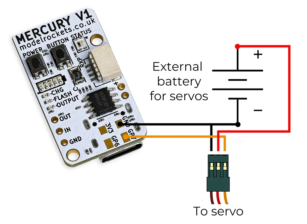
Example wiring for the GP7 solder pad
Setting the mode
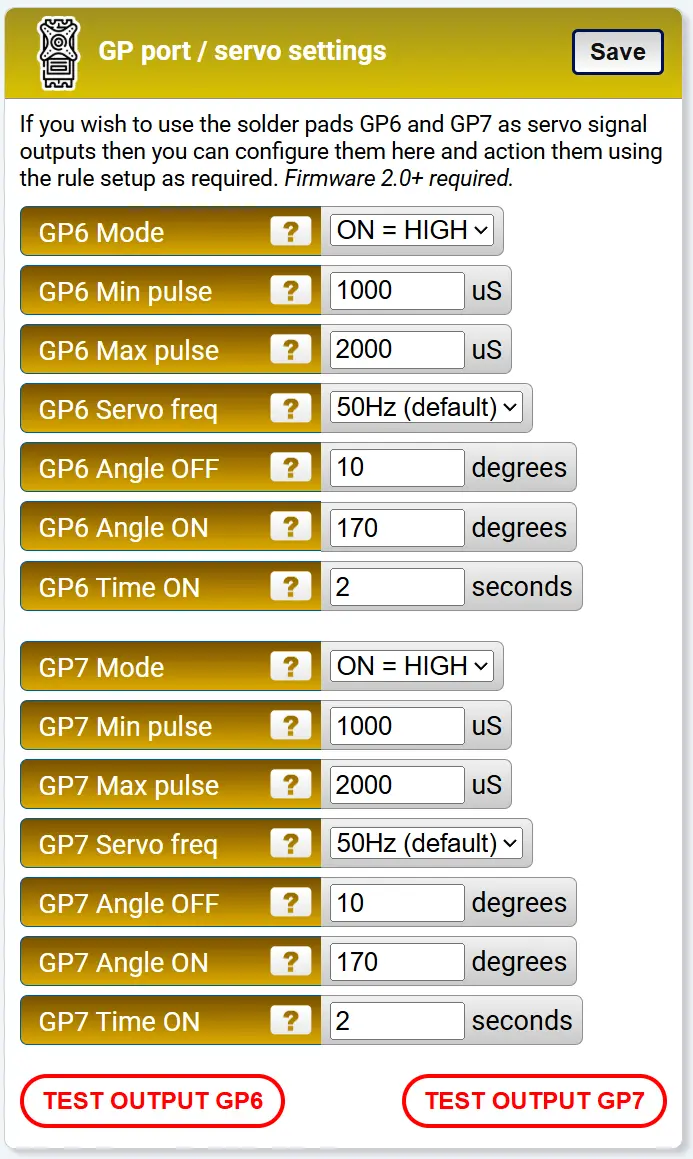
The GP port settings on the settings page

Change the Mode for each pad you wish to use to SERVO
Each pad has three mode options:
- ON = HIGH — standard output, goes high (3.3V) when triggered
- ON = LOW — standard output, goes low (0V) when triggered
- SERVO — outputs a PWM servo signal when triggered
Configuring the servo
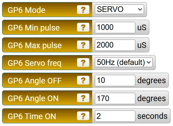
The servo settings for each GP channel
Once the mode is set to SERVO, the following settings appear for each channel:
Min pulse (µS) — the minimum width of the servo signal pulse. Check your servo's data sheet for this value. The default works for most standard servos.
Max pulse (µS) — the maximum width of the servo signal pulse. Again, check your servo's data sheet if needed.
Servo frequency — most standard servos operate at 50Hz, although faster servos are available. The options are 50Hz (default), 200Hz, 333Hz, and 560Hz. Each GP channel can have its own frequency.
Angle OFF — the angle the servo moves to when it is not being triggered by a rule. This is the resting position.
Angle ON — the angle the servo moves to when triggered by a rule. This is the active position.
Time ON — how long the servo should stay at the ON angle when triggered, in seconds. Set this to a high value (e.g. 99999) if you want it to stay on for the entire flight. You can also use the Latch ON/OFF trigger types in the action rules for more control.
Feel free to click the test button once everything is connected to check it works and see if the positions you've set are right for your needs.
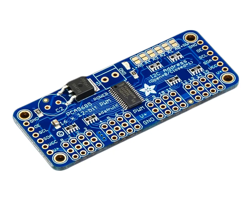
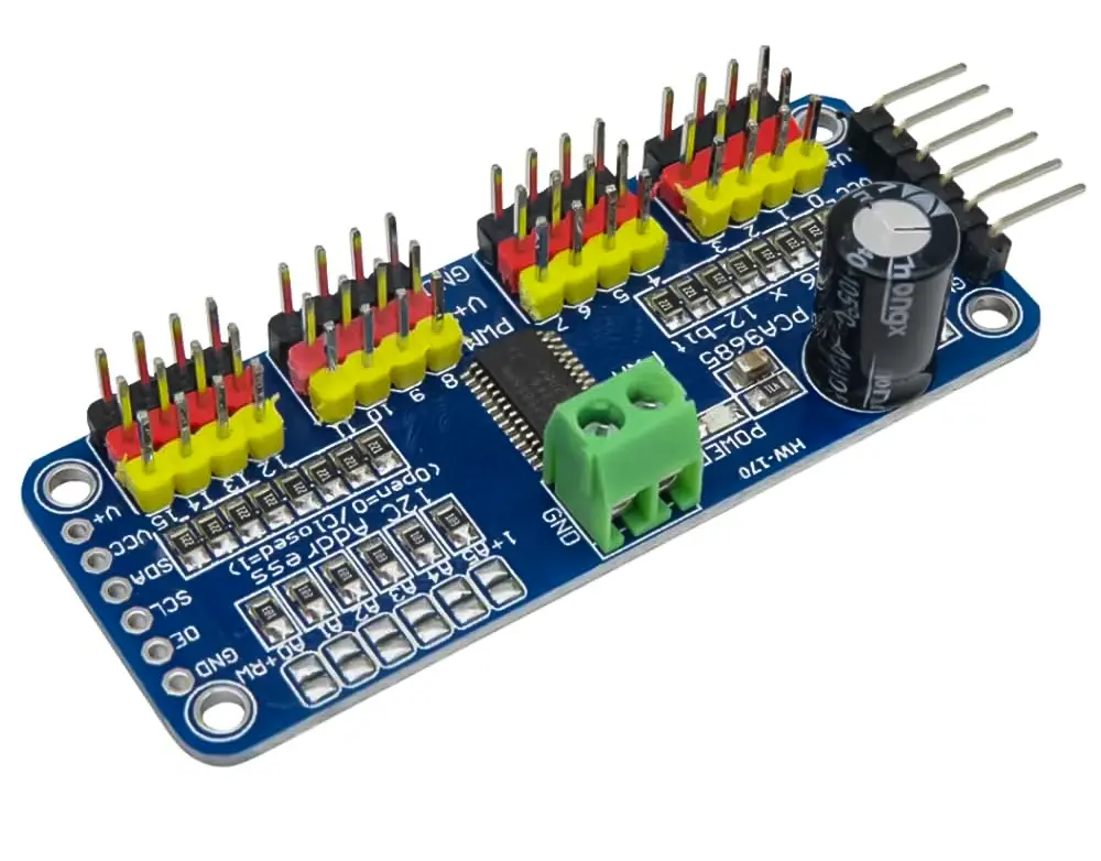
Option 2: I2C PCA9685 expansion board
If you don't want to solder to your Mercury, or need more than 2 servo channels, you can use an external I2C servo board. The Mercury is compatible with PCA9685-based boards, which are widely available and inexpensive. You can use the first 6 servo channels with your Mercury and configure them in the settings. Requires firmware 2.0 or later.
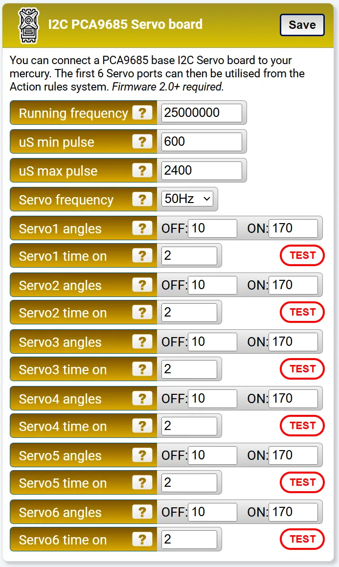
The configuration block for I2C servo boards
Board settings
Running frequency — the PCA9685 has an internal oscillator that can run from 23 to 27 MHz. The default of 25 MHz is right in the middle and works well for most boards. You can fine tune this frequency if you measure your board's actual oscillator speed, although this is not essential.
Min pulse (µS) — the minimum servo signal pulse width. All servos on the I2C board share this setting, so they need to have the same specification.
Max pulse (µS) — the maximum servo signal pulse width. Shared across all channels like the min pulse.
Servo frequency — the PWM frequency for all channels. Options are 50Hz (default), 200Hz, 333Hz, and 560Hz. All servos on the board run at the same frequency.
External CMOS clock
Ext clock — the PCA9685's internal oscillator is not entirely precise. If your board has an external CMOS oscillator connected to the EXTCLK pin, you can switch to using it for more accurate and stable servo timing. Set this to "External CMOS" and adjust the running frequency above to match your external oscillator (e.g. 25000000 for a 25 MHz oscillator). Leave on "Internal (default)" if your board does not have an external clock fitted.
Per-channel angles
Each of the 6 servo channels has its own OFF and ON angle settings, just like the GP pads. Set the OFF angle to your resting position and the ON angle to the active position. The action rules system then controls which servos are triggered and when, using the I2C Servo #1 through #6 actions.
Recommended boards
We have tested with the following two boards.
Amazon PCA9685 board — £5.99 (at the time of writing)
This inexpensive board works well and is a great budget option.
Adafruit PCA9685 board — £14.40 (at the time of writing)
A well known electronics brand version with good documentation.