Calculating a flights motor impulse from the flight data
It is possible to calculate a motor's impulse from a rocket's flight log as long as a few conditions are met. The flight log needs an IMU, and the flight needs the rocket's loaded mass and the propellant mass.
 It is possible to calculate a motor's impulse from a rocket's flight log as long as a few conditions are met. The flight log needs an IMU, and the flight needs the rocket's loaded mass and the propellant mass.
Every IMU flight on the site draws the motor's thrust in newtons from the flight's own data. Nothing is taken from the motor's published curve except its masses. The shape of the curve, the burn time and the impulse are what your flight recorded.
What the accelerometer actually sees
An accelerometer does not measure gravity. It measures the force reaching it through the airframe, per unit of mass. On the pad that force is the rod and the blast deflector holding the rocket up, which is why it reads 1 G sitting still. Off the pad only two things push on the rocket: the motor and the air. So in flight the accelerometer reads thrust minus drag, per unit of mass, along the airframe. Gravity never appears in the reading, and the reading is the same whichever way the rocket is pointing.
a = (T − D) / m so T / m = a + D / m
where a is the reading, T the thrust, D the drag and m the mass at that instant. Everything that follows is about finding the two things on the right that the sensor does not give directly: the drag, and the mass.
We use the size of the reading rather than any one axis, so it does not matter how the altimeter is mounted or whether it slipped in the bay. The size alone cannot say whether thrust or drag is winning though, and in a loose altimeter no axis can be relied on to say it either. TrueFuse uses the gyro for attitude, and that is what tells the two apart and supplies the sign. In an altimeter fixed solidly in the airframe the thrust axis stays known, so it should be possible to get good results without a gyro, though we have not tested that. The side force on a stable airframe at a small angle of attack is small against either during the burn, and is left in the reading.
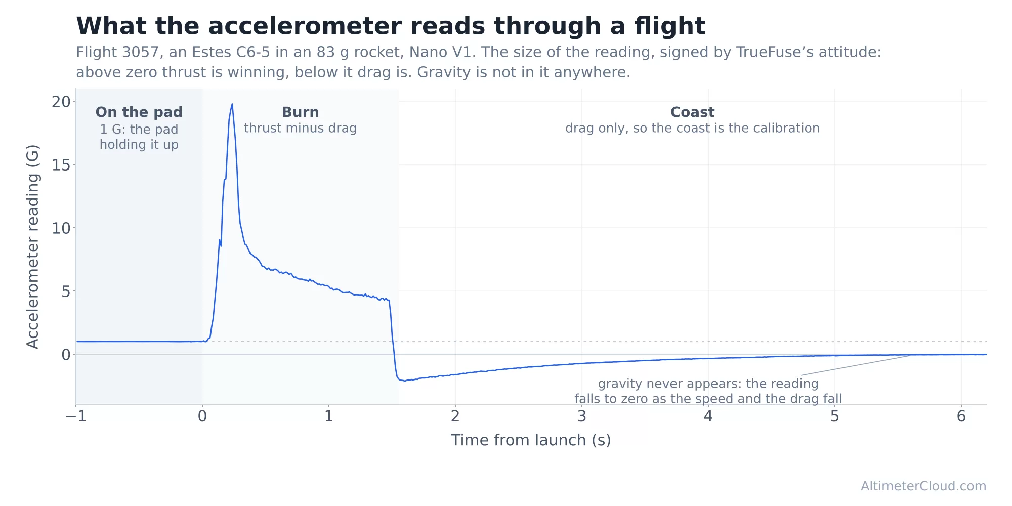
Flight 3057 by Bernard C, an Estes C6-5 on a Nano V1: 1 G on the pad from the deflector, the burn, then the coast reading drag alone and falling to zero as the speed falls.
The coast is the calibration
After burnout the motor is doing nothing, so everything the accelerometer reads is drag. Drag goes with air density times speed squared, and per unit of mass it collapses to one constant for the airframe:
D / m = k ρ v² with k = Cd A / 2m
In the coast T is zero, so the reading is simply a = −k ρ v². A straight line fit of the coast deceleration against density times speed squared, through the origin because the physics says there is nothing else in it, gives k for that flight, arranged so an ejection charge or an apogee blip cannot steer it. Nothing about the rocket's size, shape or drag coefficient is needed; the flight measures its own drag. On a flight that goes transonic the constant is fitted per Mach band instead of once, because the coast comes back down through exactly the speeds the burn went up through, and the drag coefficient is not one number through Mach 1.
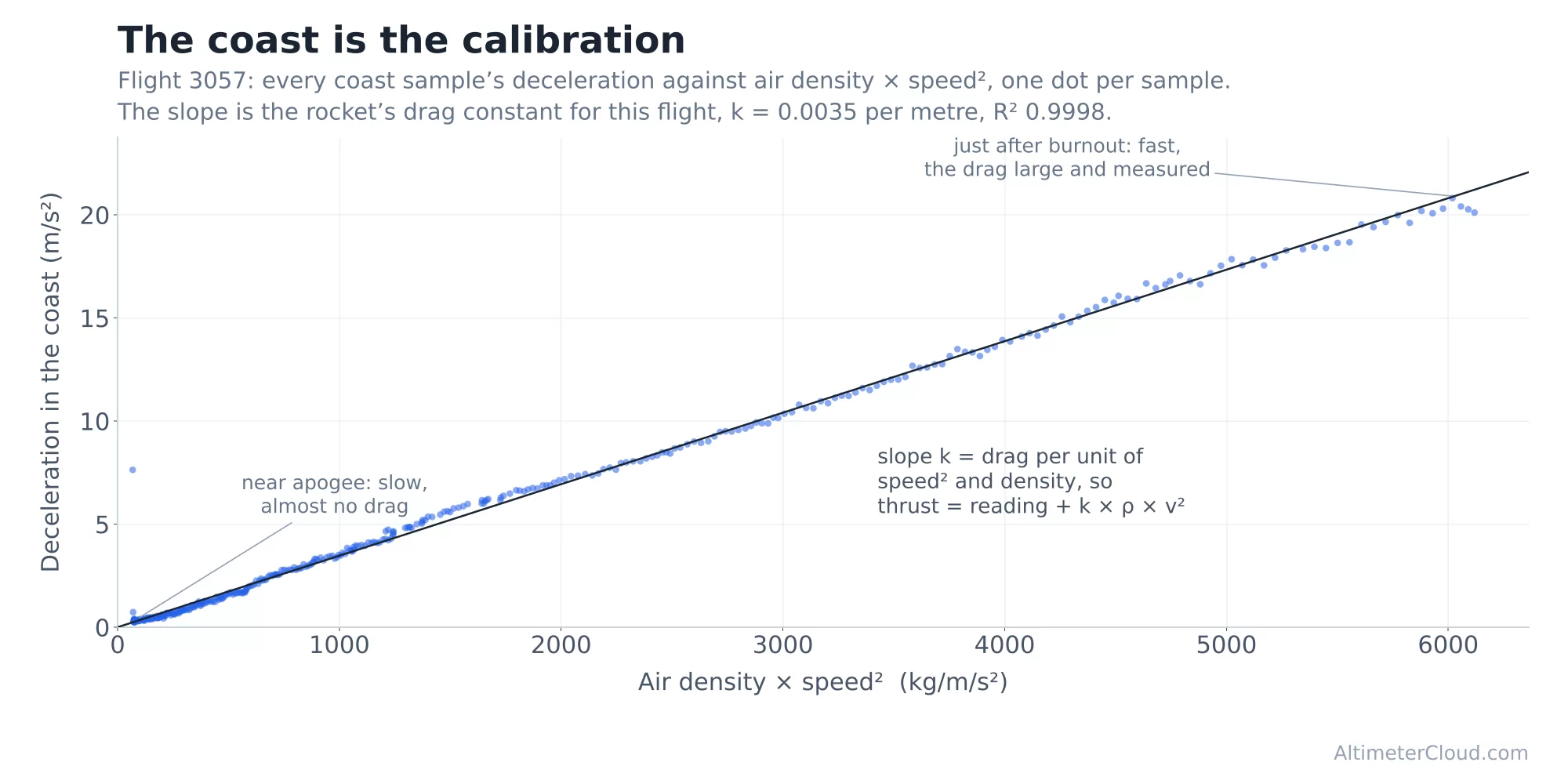
Every coast sample of the same flight: the accelerometer reading, which is the drag deceleration alone, against air density times speed squared. The slope is the drag constant, and the fit explains the coast almost perfectly.
The same constant is then added back through the burn, and what is left is the thrust alone, per unit of mass:
T / m = a + k ρ v²
Density comes from the fused altitude through the same barometric formula the site uses everywhere. Speed is the fused vertical velocity, and the next two sections are about why it has to be fused and what vertical costs. Once the constant is right the trace reads zero through the coast, and burnout, tail off and a second stage lighting can be read straight off the line. The compensation can only ever lift the burn by the drag seen just after burnout, so a trace far above the raw reading is a fault in the speed or the fit, not a stronger motor, and the fit's own statistics are kept with the flight so that can be checked rather than assumed.
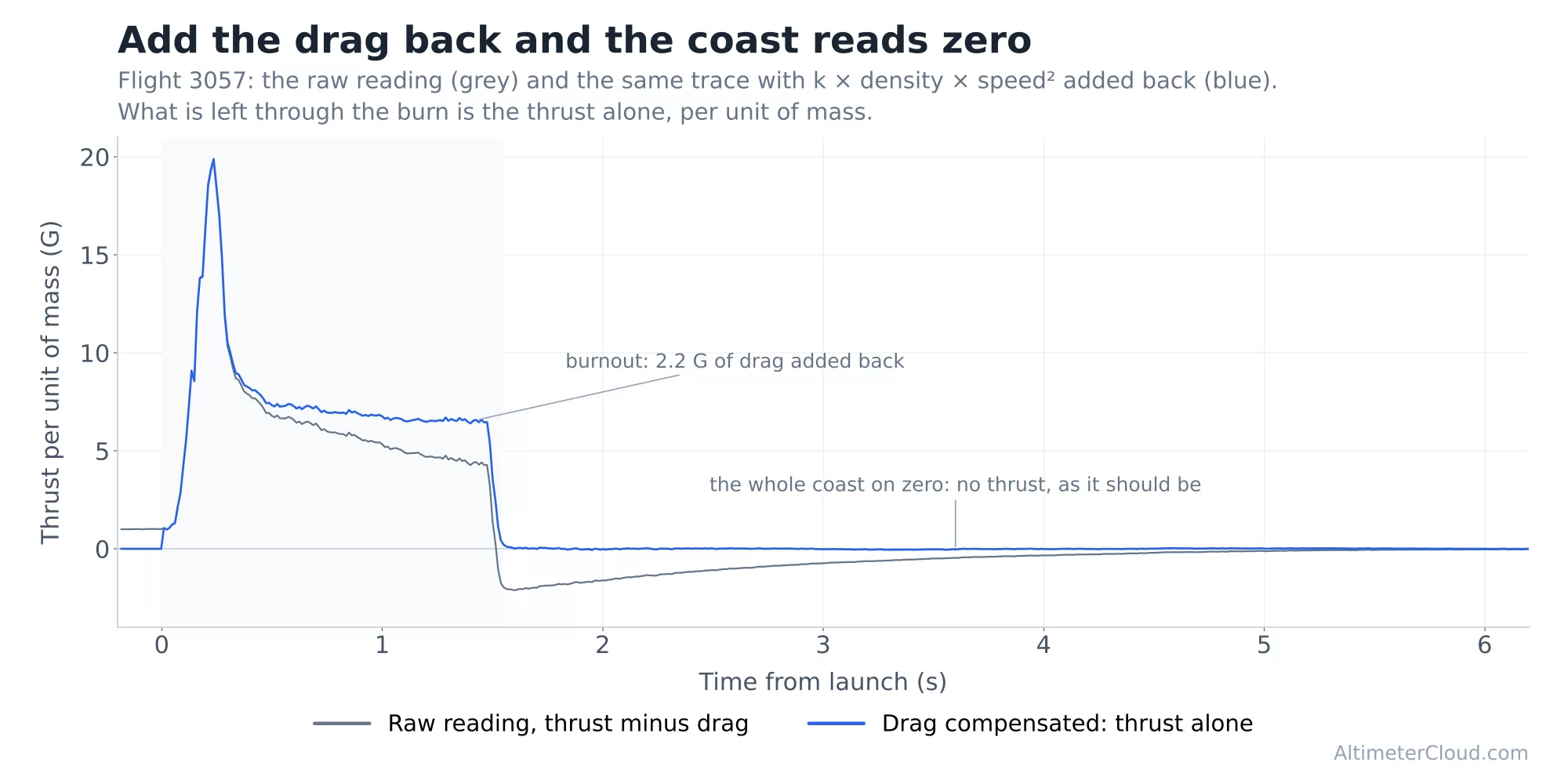
The raw reading and the drag-compensated trace. With the drag added back the coast sits on zero and the burn is lifted by the drag it was fighting.
What about the air density?
The density in the drag term is a ratio to the pad, not an absolute figure. It comes from the fused altitude above the pad through the barometric formula solved for density rather than pressure:
ρ / ρpad = (1 − L h / Tpad)n − 1
with h the height above the pad, L the standard lapse rate, Tpad the pad temperature (the altimeter's own where it logs one) and n the pressure exponent of the barometric formula, less one for the temperature that falls with it. It only says how much thinner the air is up there than where the rocket left. Because the drag constant is fitted against that same ratio, it comes out in pad density units and the real density of the day cancels: whatever the air was, the constant times the ratio times speed squared is the drag the accelerometer measured. Weather data cannot make the thrust or the impulse any more accurate, and we do not use it for this.
What the ratio does carry is the change in density between the coast, where the constant is fitted, and the burn, where it is applied. That is under ten per cent per kilometre, so a small fraction of a drag term that is itself a small part of the thrust. The one place the day's density would matter is if you wanted the rocket's drag coefficient as an absolute number, and that is a question about the airframe, not the motor.
Why the speed has to be fused
Drag goes with speed squared, so any error in the speed is doubled in the drag and goes straight into the thrust. A speed taken from pressure alone is not good enough for this, for two reasons.
The first is that velocity is the slope of the altitude, and taking the slope of a raw pressure altitude at hundreds of samples a second gives a line that is mostly noise. Smoothing it enough to be usable blurs the very thing the fit depends on, the sharp change at burnout, and lags the real speed through the burn.
The second is that the barometer is at its least trustworthy exactly where the speed matters most. The pressure rise at ignition, airflow over the vent holes at speed, and the ejection charge all land in the burn and the early coast, and those are the moments where the drag is largest and the fit is decided. A pressure-only speed through that part of the flight can be out by a large fraction, and squared that is a drag constant that is wrong for the whole flight.
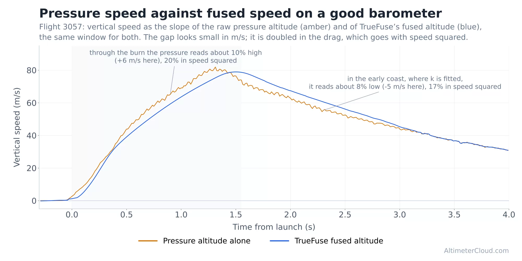
A good barometer, the Nano on flight 3057: the pressure speed reads about ten per cent high through the burn and several per cent low in the early coast. Small in m/s, doubled in the drag.
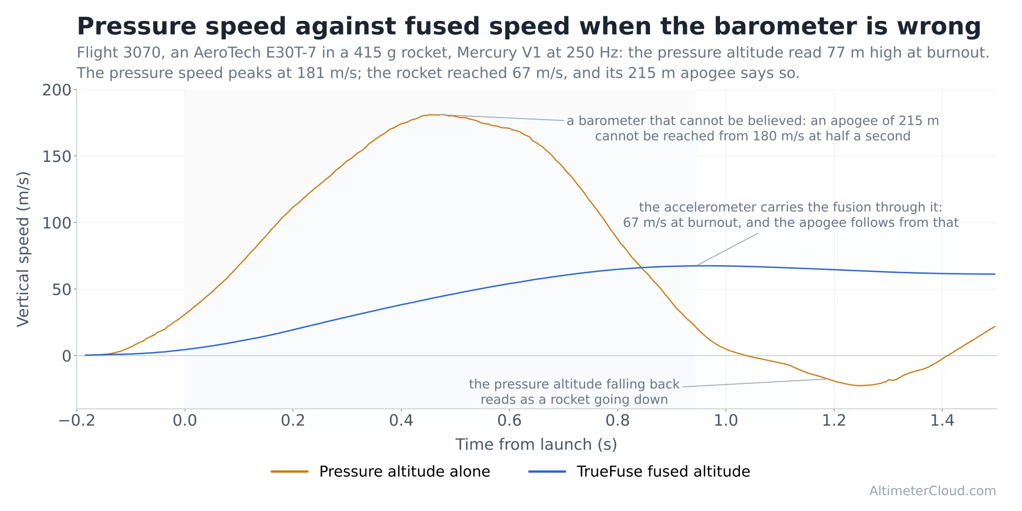
A barometer that cannot be believed, a Mercury V1 on flight 3070: the pressure altitude read 77 m high at burnout, so the pressure speed peaks at 181 m/s on a rocket that reached 67. The fused speed carries straight through it.
TrueFuse carries the accelerometer's own velocity through those moments, which is smooth and immediate sample to sample, and holds it to the barometric altitude over the longer term so it cannot drift. The vertical velocity taken from that fused altitude has the accelerometer's sharpness and the barometer's anchoring, and it is the same velocity the altimeter's own velocity column follows. Because the drag constant is fitted against it in the coast and added back with it through the burn, the one velocity is used consistently on both sides of the law.
Rocket speed or vertical speed?
Strictly, drag wants the rocket's speed along its path through the air, and what the fusion carries is the vertical component of it. The two are related by the flight path angle γ from vertical:
v = vz / cos γ
We take cos γ as 1 and use the vertical speed on both sides of the law, and that is a deliberate choice. Because k is fitted against vz² in the coast, a tilted flight simply fits a larger constant, k / cos²γ, and when that constant is applied through the burn against the same vz² the tilt cancels out of the thrust. A steady tilt costs nothing. What is left is the change of angle between the burn and the coast: the drag added back through the burn is off by the ratio of cos²γ in the burn to cos²γ in the coast. A rocket that leaves the rail at five degrees and has arced to ten by the time the fit is made is out by about two per cent on the drag term, which is under half a per cent of the impulse. One that weathercocks from ten to twenty degrees is out by about ten per cent on the drag, around one and a half per cent of the impulse, always reading high.
We did try the full version. The angle can be read from the direction of the specific force against the vertical, but exactly where thrust and drag are nearly equal the size of the reading is close to zero and its direction is sensor noise, and the drag added back jumped by more than the whole drag it was correcting. The vertical speed version has no angle noise in it, its coast residual is half the size, and the fitted drag constants agree with the figures the altimeters work out for themselves in flight. Exact in principle but noisier in practice is the wrong trade for a measurement, so the law uses the vertical speed and accepts a per cent or so on a badly weathercocked flight.
From G to newtons
The trace so far is thrust per unit of mass. To get newtons we need the mass at each instant, and the mass is falling as the propellant burns. With a constant effective exhaust velocity c the propellant goes in step with the thrust:
dm / dt = −T / c so m(t) = m0 e−A(t) / c where A(t) = ∫ (T / m) dt
A(t) is just the trace integrated from liftoff, the velocity the motor has delivered so far, so the mass at any moment is the starting mass scaled down by the thrust delivered up to then. The exhaust velocity is the one value that makes the propellant burned over the whole burn equal the motor's propellant mass mp:
c = Aburn / ln( m0 / (m0 − mp) )
Multiply the trace by the mass and you have thrust in newtons, T(t) = m(t) × (T/m)(t). The measured impulse is the propellant mass times that exhaust velocity, I = mp c, and dividing c by g gives the motor's effective specific impulse on this flight.
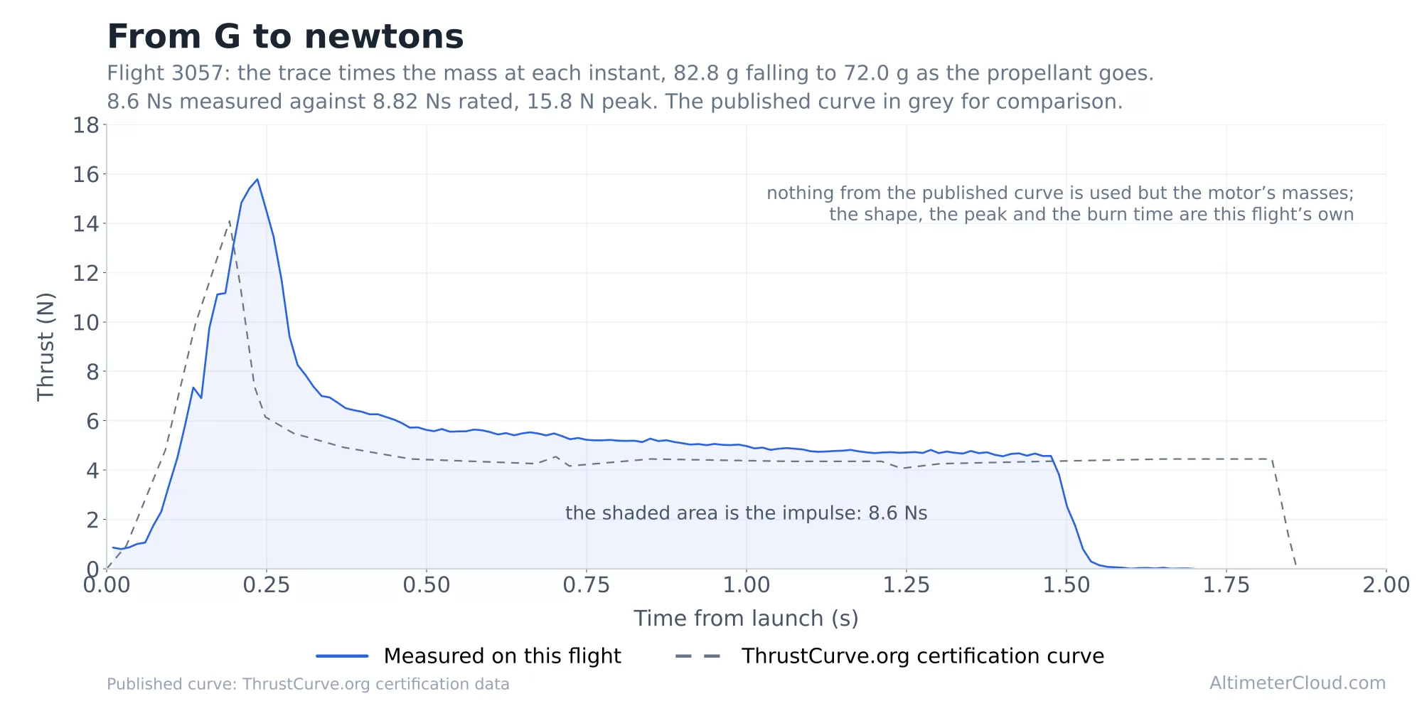
Flight 3057: the mass through the burn, 82.8 g falling to 72.0 g, dropping fastest at the thrust peak.
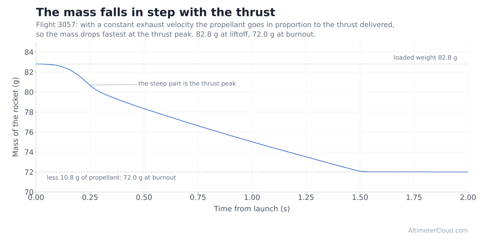
The result in newtons against the ThrustCurve.org certification curve: 8.6 Ns measured against 8.82 Ns rated, with the shape, the peak and the burn time this flight's own.
The standards behind the figures
Motors are rated under NFPA 1125 (Thank you for the tip Bernard Cawley), the US code for the manufacture of model rocket and high power rocket motors, and the impulse and burn time on the flight page follow its definitions so the comparison with the rating is like for like. Clause 7.8.3: the propellant burn time runs from where the thrust first rises above 5 per cent of its eventual peak to where it falls below 5 per cent of peak. Clause 7.8.5: the total impulse is measured from that 5 per cent rise to the last measurable thrust before ejection or blow-through, or for a plugged motor to where all action has ceased. The delay (7.8.4) is timed from the 5 per cent fall to ejection. We show the absolute figure, every newton from liftoff to the end of thrust, beside the NFPA one. Where the thrust passed 5 per cent of peak while the pad was still holding the rocket, the NFPA window opens at liftoff and the page says so.
The same code sets the tolerance a production lot is allowed (7.8.6): a model rocket motor may vary up to 20 per cent from its established mean total impulse, a high power motor 10 per cent, and a delay by 1.5 seconds or 20 per cent, whichever is greater, up to 3 seconds. A flight reading a couple of per cent under the rating is not evidence of an underperforming motor. It is a motor well inside what its certification allows, measured by a method that has a per cent or two of its own, and the flight page now says on the rated line whether the measurement sits inside that tolerance.
In North America the testing is done by the National Association of Rocketry's Standards and Testing committee (model rocket motors, and lately some high power), by Tripoli Rocketry Association's motor testing programme (high power) and by the Canadian Association of Rocketry. The three accept one another's certifications, and the Australian Model Rocket Society certifies for its own market. The curves and figures we compare against are their published certification data, by way of ThrustCurve.org. The impulse classes come from the same family of codes: A is 1.26 to 2.50 Ns and each letter after it doubles, with 1/2A and 1/4A below. A motor's designation is its class letter followed by its average thrust in newtons over the NFPA burn time, which is how the page arrives at "measured as E34" for a motor sold as an E30.
In the UK and the EU motors are pyrotechnic articles, category P1 or P2 depending on the motor, under the Pyrotechnic Articles Directive 2013/29/EU and the UK's Pyrotechnic Articles (Safety) Regulations 2015, and have to be CE marked to be sold. The harmonised standard for them is EN 16263, Pyrotechnic articles, Other pyrotechnic articles, whose test methods (Part 4) require a rocket motor's peak thrust, impulse and burn time to be measured and recorded against the manufacturer's stated tolerances. It is a safety and conformity standard rather than a rating one, so the figures on the label and the published curve still come from static tests by the manufacturer or one of the certification bodies above, and it is those we compare a flight against.
On a staged flight each stage lights at its ignition stamp and the stage below, its airframe and its spent casings, is dropped at that moment, so the mass starts over for the next stage.
Testing it
Here are a few flights with their rocket lift of weights entered from the website, and their motors specified.
The red lines are the motors calculated thrust in newtons, the black lines are the acceleration magnitude and the green dashed line is a overlay of the thrustcurve.org data for the motor.
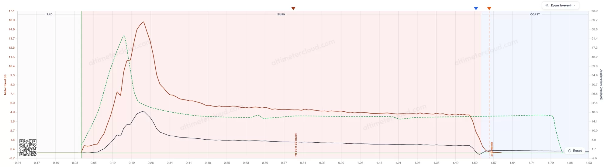
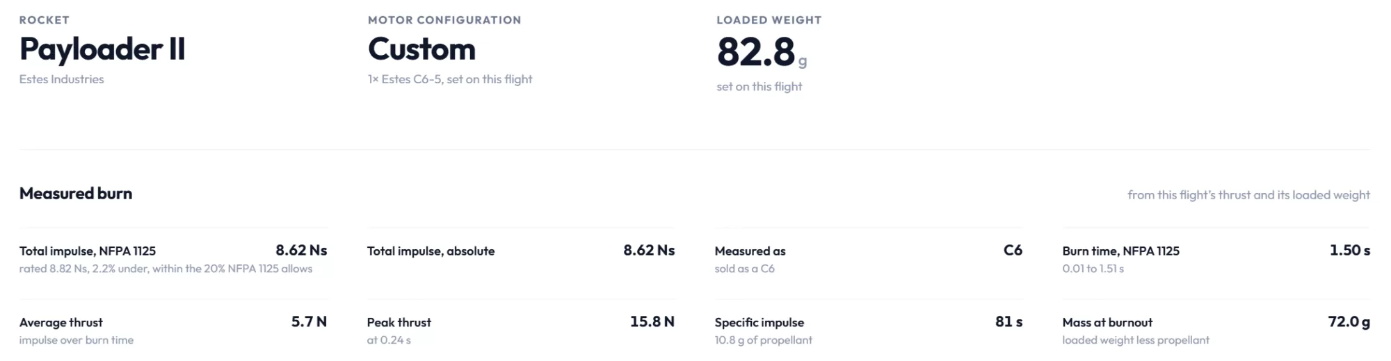
This is flight 3057 and is a Estes C6. Thrustcurve.org reports an expected 8.82 Ns of impulse, and the flight log data calculates at 8.62 Ns which is incredibly close.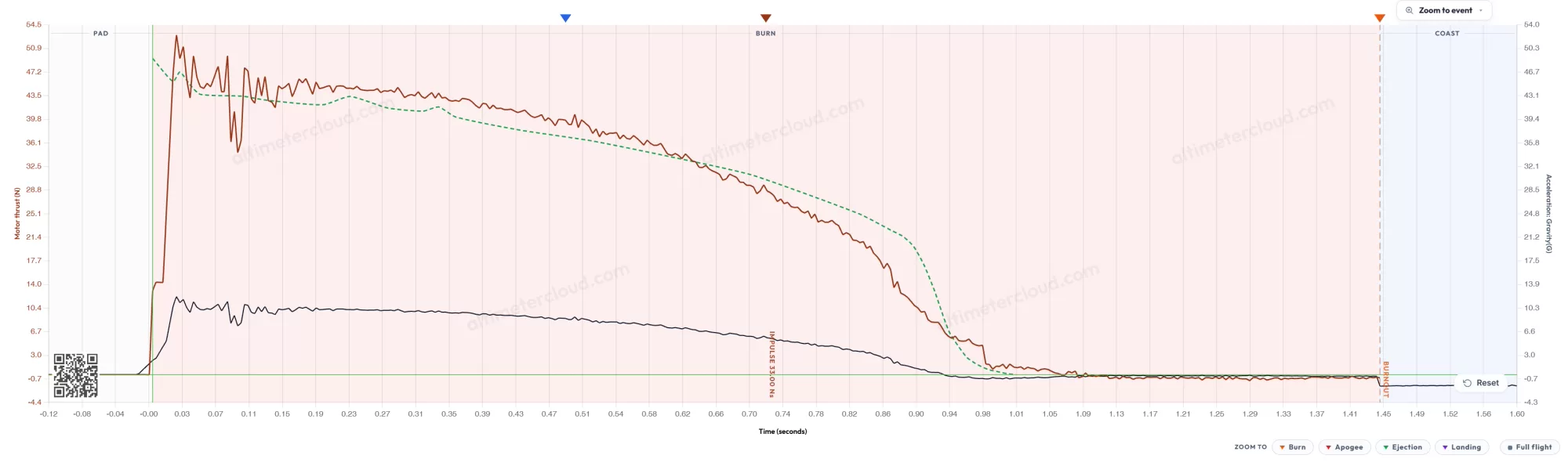
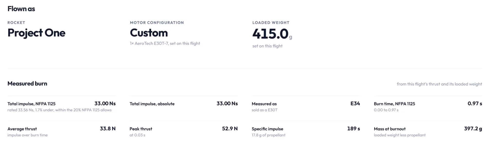
This is flight 3070 and is a Aerotech E30T-7. Thrustcurve.org reports an expected 33.56 Ns of impulse, and the flight log data calculates at 33.00 Ns, another impressively close result.
The results have verified our method, and as more users enter motors and weights we will be able to further verify.
What it needs, and what it cannot see
- The rocket's loaded mass and the motor's propellant mass. The newton figure scales directly with the loaded mass; the shape of the curve and the burn time do not. One per cent out on the mass is one per cent out on the impulse.
- A coast long enough to fit the drag. Without one the trace is drawn uncompensated and the chart says so.
- Drag is one constant for a subsonic flight. The drag coefficient is not one number through Mach 1, so when the coast is fast enough for that to matter the constant is fitted per Mach band from the same coast and the burn is compensated at the Mach it was at. The very top of the speed range, between burnout and where the coast fit can start, carries the nearest band’s value.
- A constant exhaust velocity through the burn. Real motors vary a little, which moves where the mass is lost within the burn but not the impulse, which is set by the propellant mass.
- An accelerometer with range to spare. A motor that pushes the reading past the sensor’s full scale has its peak clipped, and the impulse then reads low by whatever was above the limit. The Nano reads to 32 G.
- Enough samples through the burn. A thrust peak only a sample or two wide is under-read; that costs peak thrust far more than impulse, which is an integral and forgives it.
- Propellant burned before the rocket leaves the pad is not seen. It is the short rise to the rocket's weight and small against the burn.
- Tilt. A steady tilt cancels out of the law; only a change of angle between burn and coast is left, a few per cent of the drag term and a fraction of a per cent of the impulse, as above.